
Table of contents: Installation location of the engine… ↓ Installation location of the gas… ↓ Installation location of brake light… ↓ Installation location of the pump… ↓ Coolant temperature sensor… ↓ Coolant temperature sensor… ↓ Installation location of the Hall… ↓ Installation location of… ↓ Installation location of the engine… ↓ Installation location of the boost… ↓ Installation location of the boost… ↓ Installation location of the… ↓ Installation location of the neutral… ↓ Installation location of the… ↓ Installation location of the brake… ↓
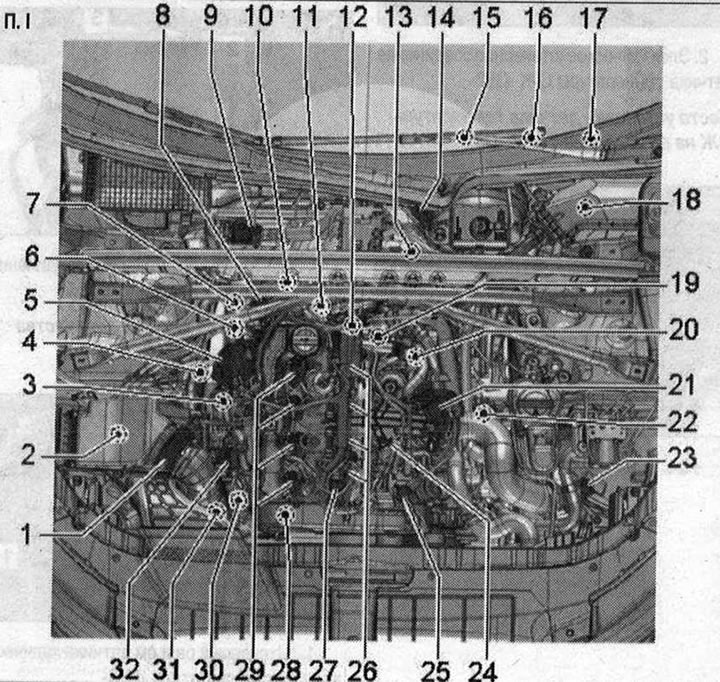
Installation location of the injection system. I 1. Air flow meter "G70"; 2. Air filter bypass valve "N₂75": domestic market version; 3. Plug connectors: for lambda probe "G39"; for exhaust gas temperature sensor 3 "G495"; 4. Lambda probe "G39" with heating element of lambda probe "Z19"; 5. Executive motor for exhaust gas recirculation "V338" with potentiometer for exhaust gas recirculation "G212": integrated into the radiator for exhaust gas recirculation; 6. Sensor 3 exhaust gas temperature "G495"; 7. Coolant temperature sensor at the radiator outlet "G83"; 8. Differential pressure sensor "G505"; 9. Coolant circulation pump "V50": only vehicles with start-stop system; 10. Sensor 4 exhaust gas temperature "G648" 11. Coolant temperature sensor "G62"; 12. Fuel pressure regulating valve "N₂76"; 13. Gearbox neutral position sensor "G701": only vehicles with start-stop system; 14. Brake booster pressure sensor "G294"; 15. Accelerator pedal position sensor "G79" and accelerator pedal position sensor 2 "G185"; 16. Brake light switch "F" and brake pedal sensor "F47"; 17. Clutch pedal position sensor "G476": with clutch pedal position sensor for engine start "F194" and clutch pedal position sensor "F36" (only in cars with manual transmission); only in cars with manual transmission; 18. Used engine "J623"; 19. Engine speed sensor "G28"; 20. EGR radiator pump "V400"; 21. Throttle control module "J338" with throttle potentiometer "G69"; 22. Left solenoid valve for electrohydraulic engine mount "N144": left only; 23. Boost pressure sensor "G31" / intake air temperature sensor "G42"; 24. Fuel temperature sensor "G81"; 25. Fuel metering valve "N₂90"; 26. Glow plugs: Glow plug 1 "Q10". Glow plug 2 "Q11". Glow plug 3 "Q12". Glow plug 4 "Q13"; 27. Fuel pressure sensor "G247"; 28. Hall sensor "G40"; 29. Injectors: Injector of cylinder 1 "N30". Injector of cylinder 2 "N31". Injector of cylinder 3 "N32". Injector of cylinder 4 "N33"; 30. Electromagnetic boost pressure limiting valve "N75"; 31. EGR radiator changeover valve "N345"; 32. Boost pressure regulator position sensor "G581"
Installation location of the engine control unit "J623"

In the switch block on the left in the water drainage box.
Installation location of the gas pedal position sensor "G79" and gas pedal position sensor 2 "G185"

In the accelerator pedal module. The accelerator pedal position sensor "G79" and the accelerator pedal position sensor 2 "G185" are integrated into the accelerator pedal module and cannot be replaced separately.
Installation location of brake light switch "F" and brake pedal sensor "P47" / clutch pedal position sensor "G476"
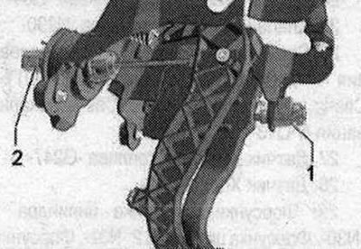
- 1. Brake light switch "F" and brake pedal sensor "F47"
- 2. Clutch pedal position sensor "G476" with clutch pedal position sensor for engine start "F194" and clutch pedal position sensor "F36" (only in cars with manual transmission)
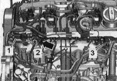
Installation locations 1. Fuel pressure sensor "G247"; 2. Fuel temperature sensor "G81"; 3. Fuel pressure regulating valve "N₂76"
Installation location of the pump for the recirculation cooler 0G "V400"
On the rear left side of the engine.

- 4. Electrical plug connection of the EGR radiator pump "V400"
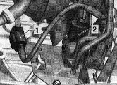
Coolant temperature sensor installation location "C62"
On the back of the engine.

- 2. Electrical plug connection of coolant temperature sensor "G62"
Coolant temperature sensor installation location at radiator outlet "GB3"

"Pos. 1" in the coolant pipe at the rear.
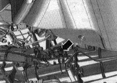
Installation location of the Hall sensor "G40"

At the front of the engine, next to the camshaft timing belt gear, there is an "arrow".
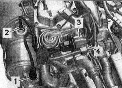
Installation locations 1. Lambda probe "G39"; 2. Sensor 3 exhaust gas temperature "G495"; 3. Electrical plug connection of the lambda probe "G39"; 4. Electrical plug connection of the exhaust gas temperature sensor 3 "G495"
Installation location of differential pressure sensor "G505"
On the back of the engine.

- 3. Electrical plug connection of the differential pressure sensor "G505"
Installation location of the engine speed sensor "G28"

- 1. Plug connector of the engine speed sensor "G28"
Installation location of the boost pressure sensor "G31" with the intake air temperature sensor "G42"
Front left in the engine compartment.

- 1. Electrical plug connection of the boost pressure sensor "G31" with the intake air temperature sensor "G42"
Installation location of the boost pressure regulator position sensor "G581"
The turbocharger is on the right side of the engine.

- 1. Electrical plug connection of the position sensor of the boost pressure regulator "G581"
Installation location of the electromagnetic valve of the boost pressure limitation "N75"

On the front right side of the engine there is an arrow.
Installation location of the neutral position sensor of the gearbox "G701"
On the left on the gearbox "arrow". Installed only on cars with a start-stop system.
Electrical plug connections 1. Sensor 1 exhaust gas temperature "G235"; 2. EGR radiator changeover valve "N345"
Installation location of the solenoid valve of the left electrohydraulic engine support "N144".

On the engine support on the left there is an "arrow", (el. plug connection).
Installation location of the brake booster pressure sensor "G294"

There is an arrow in the vacuum line to the brake booster.
[This article was copied from an online resource: audimanual.ru]