
Caution! Risk of engine malfunction. When laying vacuum hoses, avoid bending, twisting or pinching them.
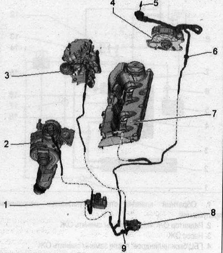
Vacuum hose connection diagram 1. Electromagnetic boost pressure limiting valve "N75"; 2. Turbocharger: with vacuum reservoir; with the boost pressure regulator position sensor "G581"; 3. EGR cooler changeover valve vacuum reservoir; 4. Vacuum pump; 5. To the brake booster; 6. Check valve: install in proper position; 7. Cylinder head cover: with vacuum receiver; 8. EGR radiator changeover valve "N345"; 9. Check valve: install in proper position