
Table of contents: Mounting position of the clamping… ↓ Carrying out adaptation of… ↓
Caution! When installing a new engine, after installing the high-pressure lines, it is necessary to tighten the clamping brackets of the injectors to the prescribed torque. To align the injectors when installing the high-pressure lines, tightening the clamping brackets is allowed only "by hand". Inattention may lead to engine damage.
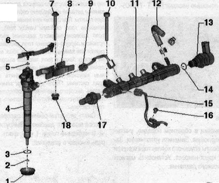
Injection nozzles 1. Sealing cuff: in the cylinder head cover; 2. Copper sealing ring: replace; 3. Sealing ring: replace; 4. Injector: When reinstalling removed injectors, high-pressure lines and clamps, install them only on the cylinder from which they were removed.; 5. Sealing ring: replace; 6. Return fuel line: to the fuel tank; with throttle valve; must not be bent, damaged or clogged; do not disassemble; the function of the throttle valve is to maintain residual pressure in the return fuel lines; this control quantity is needed for the injectors to function; after replacement, let the engine idle for 2 minutes to remove air from the fuel system and then check the return fuel lines for leaks; 7. Bolt: replace; 8 Nm + 180°; 8. Clamping bracket: for reinstallation, mark the conformity, when installing, take into account the marking; 9. High pressure line: between the fuel distributor and the injectors; install freely; lubricate the threads of the union nuts with clean oil; 25 Nm; 10. Bolt; 22 Nm; 11. Fuel distributor; 12. Return fuel hose; 13. Fuel pressure regulating valve "N₂76": replace after each dismantling; 80 Nm; after replacing the high-pressure pump or the fuel pressure regulating valve "N₂76", it is necessary to carry out a repeated adaptation; 14. Sealing ring: replace; 15. High pressure main; between the high pressure pump and the fuel distributor;install freely; lubricate the threads of the union nuts with clean oil; 25 Nm; 16. Bolt: 8 Nm; 17. Fuel pressure sensor "G247": 1D0 Nm; 18. Nozzle: in the cylinder head cover
Mounting position of the clamping bracket
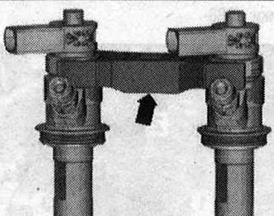
Each clamping bracket covers 2 nozzles respectively. The thickening "arrow" of the clamping bracket faces downwards.
Carrying out adaptation of correction values of fuel injection nozzles
The function of the fuel quantity adjustment (IMA) is to adjust the injection volume of fuel individually for each cylinder of the Common Rail system according to all characteristics. Seven-digit adaptation values "1" (the data in the figure is for example only) are printed on each injector. The printed values can be letters and/or numbers.
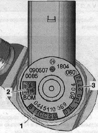
Top view of the nozzle 1. Checksumming; 2. Data Matrix Code; 3. Part number
After replacing an injector, the adaptation value must be written to the engine control unit. After replacing the engine control unit, the "adaptation values for injectors" must be transferred to the new engine control unit. Additionally, check all other injectors for "fuel value adjustment (IMA)" to ensure that all values have been entered correctly. If the engine control unit contains the correct values, they must not be re-entered under any circumstances. The adaptation procedure is described in Guided Fault Finding. (The order of actions is also described in the Guided Functions.)
[The original version of the article is posted on the website «AudiManual»]