
Table of contents: Injection modules (nozzles) ↓ Removal and installation injectors ↓ Lambda probe, exhaust gas… ↓
Injection modules (nozzles)
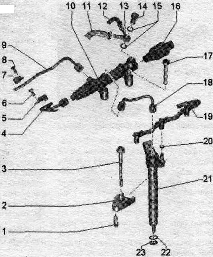
1. Clamp bracket support: different tightening torques: on the camshaft bearing 2.5 Nm, on the cylinder head 9 Nm.
2. Clamp: For reinstallation, mark the connection, when installing, take into account the designation; when changing the injector, replace it.
3. Bolt: 14 Nm.
4. High-pressure line: from the fuel injection pump to the fuel distributor; do not change the bent shape; check for damage before reinstalling; lubricate the threads of the union nuts with clean oil; 25 Nm.
5. High pressure line mounting clamp.
6. Bolt: 9 Nm.
7. High pressure line mounting clamp.
8. Bolt: 9 Nm.
9. High pressure line: located opposite the fuel. ramps; do not change the bent shape; check for damage before reinstalling; lubricate the threads of the union nuts with clean oil: 25 Nm.
10. Fuel rail.
11. Reverse fuel. hose: to the fuel tank.
12. Reverse fuel. hose: from the injectors; do not disassemble; replace complete with expansion tube; after replacement, let the engine run for 2 minutes at idle. move to remove air from the fuel. system, then check the return hoses for leaks.
13. Ring hose nipple.
14. Hollow screw: 25 Nm.
15. Sealing rings: replace.
16. Fuel pressure regulating valve "N276": with serrated edge for seal; do not reuse.
17. Bolt: 22 Nm.
18. High-pressure line: from the fuel rail to the injector; do not change the bent shape; for reinstallation, mark the connection; when installing, take into account the designation; check for damage before reinstalling; lubricate the threads of the union nuts with clean oil; 25 Nm.
19. Reverse fuel. hose: from the injectors; do not disassemble; replace complete with expansion tube; after replacement, let the engine run for 2 minutes at idle. move to remove air from the fuel. syst.; then check the return hoses for leaks.
20. Sealing ring: replace.
21. Injector: For reinstallation, mark the connection; take the marking into account when installing.
22. Sealing ring: replace.
23. Copper seal. ring: replace.
Fuel pressure regulating valve "N276" - tightening torque
Align the N276 fuel pressure regulator so that the wiring isn't routed under the rod after connecting the "arrow" connector. Tighten the union nut on the regulator in four stages as follows, holding it by the hexagon on the housing.
| Step | Tightening torque |
| 1 | screw it in by hand until it stops |
| 2 | 60 Nm |
| 3 | rotate back 90° |
| 4 | 85 Nm |
Fuel pressure sensor "G247" - tightening torque
Tighten the G247 fuel pressure sensor in 4 stages. Do not use a wrench to open or tighten.
| Step | Tightening torque |
| 1 | screw it in by hand until it stops |
| 2 | 60 Nm |
| 3 | rotate 180° |
| 4 | 85 Nm |
Perform adaptation of the fuel injection device correction values
The function of "Fuel Quantity Correction (1 MA)" and "Voltage Correction (ISA)" is to adjust the volume of fuel injected individually for each cyl. common Rail system by all characteristics. Seven-digit adaptation values "1" (example) are printed on each injector. Values can be letters and/or numbers (ASCII code).
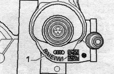
Symbol table for reading symbols on the injector.
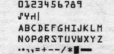
The adjustment procedure is described in "Guided Troubleshooting." Use the Tester for this. When replacing an injector, it is necessary to record its adaptation value in the engine control unit. Additionally, check the remaining injectors for "Fuel quantity adjustment (1MA)" with "Voltage adjustment (ISA)" to ensure that all adjustment values are correct. If the correct adaptation values are written into the engine control unit, they must not be re-entered. When replacing an engine control unit, the corresponding "Injector Basic Values for Injector Injection Volumes" with "Injector Basic Voltage (ISA)" must be entered into the new engine control units.
Removal and installation injectors
Remove the engine cover. Remove the air casing. filter.
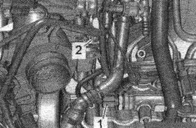
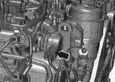
Disconnect the connectors of the "arrow" injectors and the fuel pressure regulating valve "N276" "pos. 1". Release the wiring harness on the cylinder head cover and on the fuel rail.
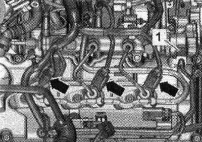
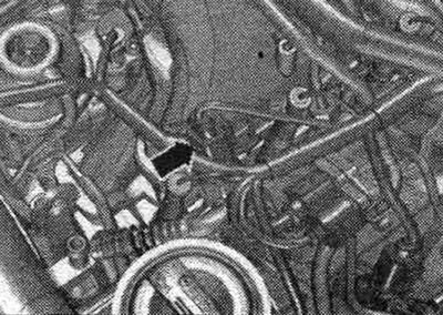
Remove return fuel. hoses from the injectors; to do this, press both tabs and at the same time pull the middle part to unlock upwards "arrow". Previously used injectors must only be installed in the same cylinder. For reinstallation, mark the compatibility of the injectors with the cylinder.
Remove the high-pressure lines by loosening union nuts "2," "3," and "4" using the "T40055" socket wrench. Open lines and fittings should be immediately sealed with a clean plug.
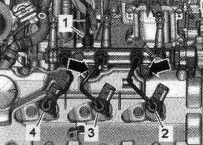
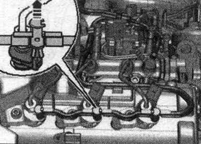
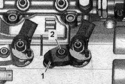
For reinstallation, color-code the nozzle and pressure plate "1" to each other. Unscrew bolt "2" and remove the pressure plate. Repeat the procedure on the remaining injectors.
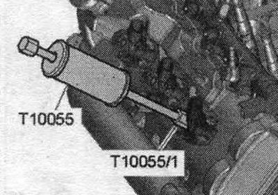
Install the puller "T10055" with the adapter "T10055/1" on the injector, as shown in the figure. Remove the injector by tapping. Place the removed injectors on a clean cloth.
Reinstalling injection nozzles
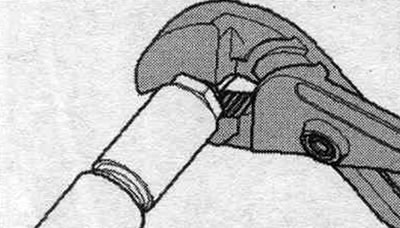
When reinstalling a used injector, the following must be replaced: copper seal. ring, sealing ring of the injector socket, sealing ring of the return line fitting. Spray rust remover onto the tip of the nozzle. After about 5 minutes, remove any rust or oil particles with a clean cloth. If the nozzle is heavily contaminated, its lower part should be additionally cleaned. clean with a soft brass brush to facilitate removal of the copper seal. Do not allow the brass brush to come into contact with the injector nozzle channel. To remove the old copper seal. carefully clamp the ring from the nozzle with pliers so that it does not turn. Using light twisting and pulling movements of your hand, remove the nozzle from the copper gasket. Remove deposits from under the copper seal. ring using a scraper.
Risk of damage to the sealing surface of the injector. To remove soot particles from the injector sealing surface, clean the injector seat in the cylinder head with a rag soaked in oil or rust remover.
Installing new injectors
When installing a new injector, it is necessary to replace: clamp, copper seal. ring, sealing ring of the injector socket, sealing ring of the return line fitting. Before installation, lubricate all seals. rings with mounting or oil.
All
Using a plastic bushing, install a new copper seal. Before installation, lubricate all seals. rings with mounting or oil. Install a new seal. injector socket ring. Installation in reverse order. Install fuel. high-pressure lines. Connect the return fuel. hoses. After replacing one or more injectors, the engine control unit must be updated with "Fuel Quantity Adjustment (IMA)" and "Voltage Adjustment (ISA)" for the new injectors.
Remove air from the fuel. system and check for leaks
Let the engine run for a few minutes at idle speed without pressing the gas pedal and then turn off the engine. To remove air, do not open the high pressure outlets, air from the system. the fuel supply is removed independently. Turn off the ignition. Check the tightness of all fuel. return line system and outlets (6 pieces). If the seal is broken, despite the correct tightening torque, replace the faulty unit. Carry out a test drive over a distance with at least one acceleration under maximum load, then recheck the high-pressure circuit for leaks. Presence of air in fuel. system during a test drive may cause the engine to operate in emergency mode. Turn off the engine and clear the fault memory. Continue with the test drive.
Lambda probe, exhaust gas temperature and pressure sensor
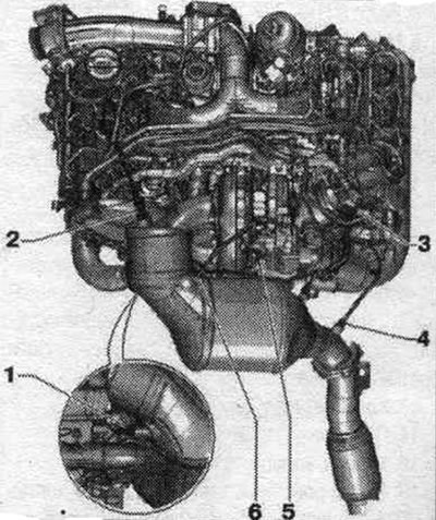
1. Pressure pipe of the differential pressure sensor "G505". 2. Lambda probe "G39" with the lambda probe heating element "Z19": new lambda probes are lubricated with mounting paste; when reusing the lambda probe, lubricate the threads with heat-resistant paste for bolts; mounting and heat-resistant pastes must not get into the grooves of the lambda probe housing; 55 Nm. 3. Differential pressure sensor "G505". 4. Exhaust gas temperature sensor 4 "G648". 5. Exhaust gas temperature sensor 1 "G235". 6. Exhaust gas temperature sensor 3 "G495".
(The original article is available on the website: AUDImanual)