
Table of contents: Schematic overview of fuel. syst. ↓ Vacuum system ↓
Schematic overview of fuel. syst.
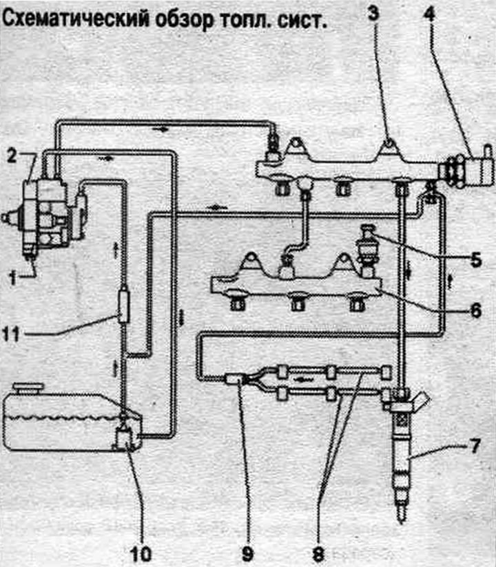
1. Fuel metering valve "N290": do not open.
2. Fuel injection pump.
3. Fuel rail: cylinder bank 1 (right).
4. Fuel pressure regulating valve "N276": do not reuse.
5. Fuel pressure sensor "G247".
6. Fuel rail: cylinder bank 2 (left).
7. Nozzle.
8. Return hoses: do not disassemble: replace complete with expansion tube.
9. Throttle: maintains residual pressure in the return fuel. hoses; cannot be replaced separately; in case of defect, replace the return hoses.
10. Fuel pump. pump "G6".
11. Fuel filter.
Vacuum system
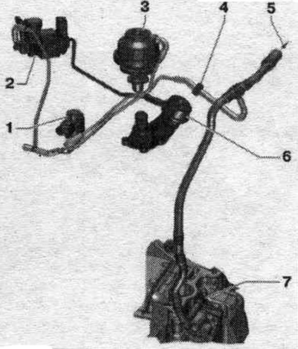
1. Radiator changeover valve system. exhaust gas recirculation "N345".
2. Cylinder head coolant valve "N489".
3. Vacuum actuator of the system cooler. exhaust gas recirculation.
4. Check valve.
5. To the brake booster. drive.
6. Shut-off valve: for coolant.
7. Connecting the vacuum line: to the top of the oil. pallet; to the vacuum pump.