
Overview of installation locations
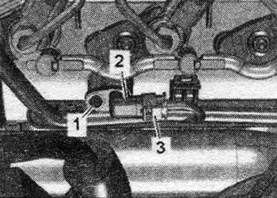
Engine compartment
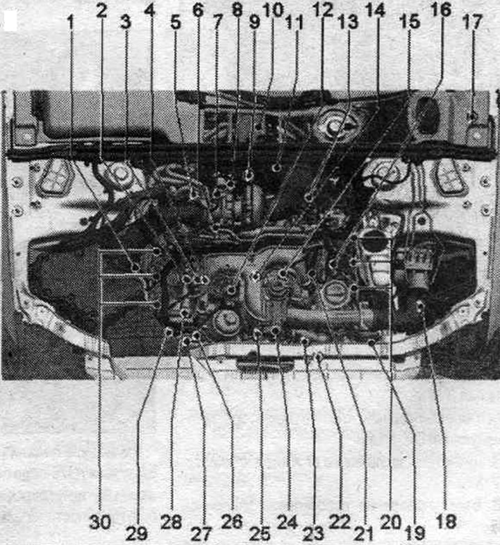
1. Air flow meter "G70".
2. Electrical connector of the temperature sensor in the system. exhaust gas recirculation "G98".
3. Plug connector of the thermostat of the electronic control of the engine cooling system "F265", the fuel metering valve "N290" and the actuator of the electric motor of the system. exhaust gas recirculation "V338".
4. Choke: in the return fuel. highways.
5. Differential pressure sensor "G505".
6. Fuel temperature sensor "G81".
7. Plug connector of exhaust gas temperature sensor 3 "G495".
8. Turbocharger control unit 1 "J724": on the turbocharger on the left.
9. Exhaust gas temperature sensor 1 "G235".
10. Charger and starting device.
11. Exhaust gas temperature sensor 3 "G495".
12. Coolant valve cylinder head "N489".
13. Lambda probe "G39" with lambda probe heating element "Z19".
14. Servo motor system. exhaust gas recirculation "V338".
15. Coolant temperature sensor "G62".
16. Plug connector of the lambda probe "G39".
17. Engine control unit "J623".
18. Boost pressure sensor "G31"/intake air temperature sensor "G42": 5 Nm.
19. Throttle control unit "J338".
20. Injectors: cylinder bank 2.
21. Fuel pressure sensor "G247".
22. Oil pressure regulating valve "N428".
23. Engine temperature controller temperature sensor "G694".
24. Intake manifold flap motor "V157".
25. Radiator changeover valve system. exhaust gas recirculation "N345".
26. Oil pressure sensor for low pressure "F378".
27. Oil pressure sensor "F22".
28. Fuel pressure regulator "N276".
29. Radiator outlet coolant temperature sensor "G83".
30. Injectors: cylinder bank 1.
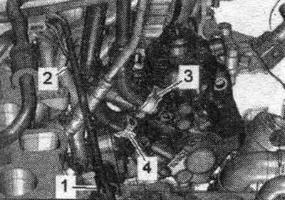
Engine on top
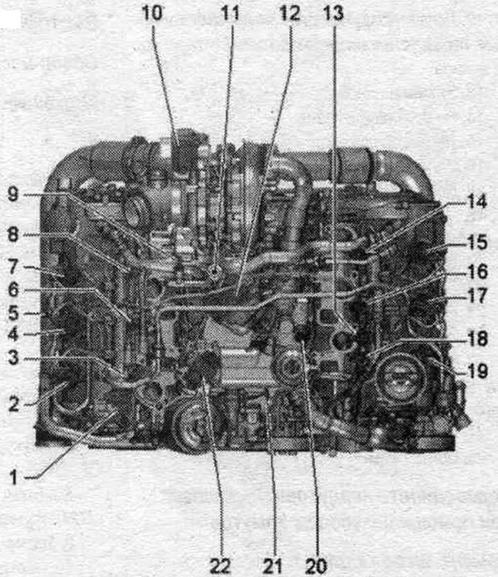
1. Fuel pressure regulating valve "N276".
2. Injector cyl. 1 "N30".
3. Glow plug 1 "Q10".
4. Injector cyl. 2 "N31".
5. Hall sensor "G40".
6. Glow plug 2 "Q11".
7. Cylinder injector. 3 "N32".
8. Glow plug 3 "Q12".
9. Fuel temperature sensor "G81".
10. Turbocharger control unit 1 "J724": on the turbocharger.
11. Fuel metering valve "N290".
12. Servo motor system. exhaust gas recirculation "V338".
13. Fuel pressure sensor "G247".
14. Glow plug 6 "Q15".
15. Cylinder injector. 6 "N84".
16. Glow plug 5 "Q14".
17. Injector cyl. 5 "N83".
18. Glow plug 4 "Q13".
19. Injector cyl. 4 "N33".
20. Coolant temperature sensor "G62".
21. Coolant valve cylinder head "N489".
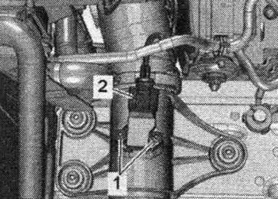
Front engine
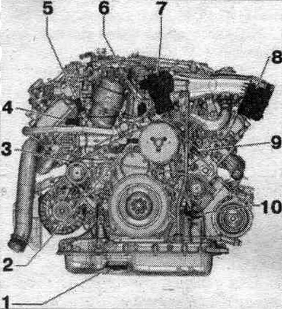
1. Oil level and temperature sensor "G266".
2. Electronic control thermostat of the system. engine cooling "F265".
3. Oil temperature sensor 2 "G664".
4. Oil pressure sensor "F22".
5. Oil pressure sensor for low pressure "F378".
6. Radiator changeover valve system. exhaust gas recirculation "N345".
7. Intake manifold flap motor "V157".
8. Throttle control unit "J338".
9. Engine temperature controller temperature sensor "G694".
10. Oil pressure regulating valve "N428".
Installation location of the engine control unit "J623"
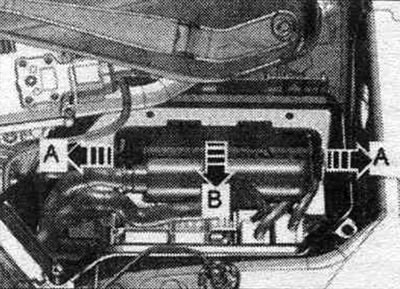
On the left there is a switch. engine compartment block.
Installation location of the accelerator pedal position sensor "G79"/accelerator pedal position sensor 2 "G185"
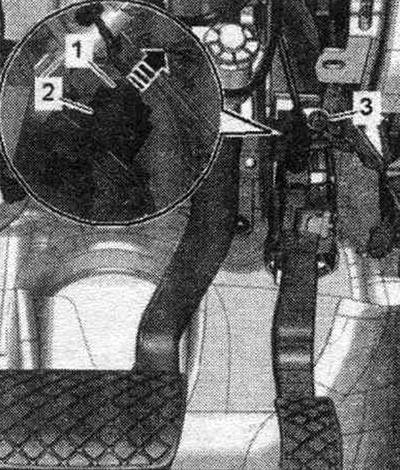
In the gas pedal module. The accelerator pedal position sensor "G79" and the accelerator pedal position sensor 2 "G185" are integrated into the accelerator pedal module and cannot be replaced separately.
The pedal block contains the following elements:
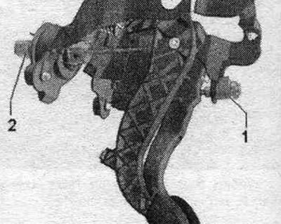
1. Brake light switch "F" and brake pedal sensor "F47". 2. Clutch pedal position sensor "G476". Integrated functions: clutch pedal position sensor for engine start "F194" and clutch pedal position sensor "F36" (only in cars with manual transmission.).
Location of fuel control unit installation. pump "J538"
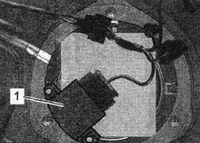
Fuel control unit. the pump "J538" "arrow" is located on the right side of the rear seat between the floor panel and the fuel tank.
Installation location of the differential pressure sensor "G505"
"Pos. 2" at the rear right of the engine.
Installation location of the Hall sensor -G4O-
"Pos. 2" on the cylinder head cover of cylinder bank 1 (on the right).
Installation location of the fuel metering valve "N290"
"Pos. 2" in the high pressure pump.
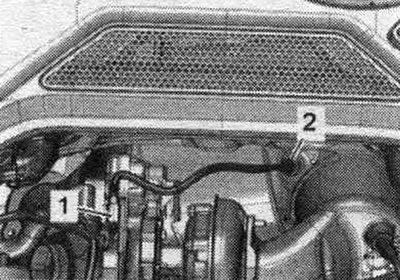
Installation location of the boost pressure sensor "G31"/intake air temperature sensor "G42"
"Pos. 2" on the air duct pipe on the left in the motor. compartment.
Engine Temperature Controller Temperature Sensor "G694"
"Pos. 1" at the front left of the cylinder block.
Installation location of the coolant temperature sensor at the radiator outlet "G83"
"Pos. 2" in front to the right of the coolant hose.
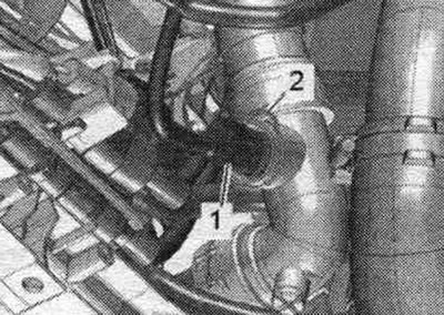
Turbocharger temperature sensor
1. Exhaust gas temperature sensor 1 "G235"
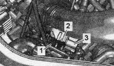
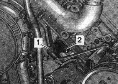
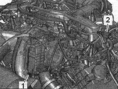
Temperature sensor
1. Plug connector of exhaust gas temperature sensor 3 "G495". 2. Exhaust gas temperature sensor 3 "G495".
[Information obtained from this resource AUDImanual.ru]