
Table of contents: Intake manifold ↓ Removal and installation the intake… ↓
Intake manifold
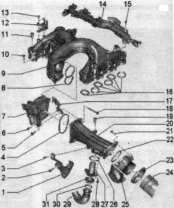
1. Air guide pipe bracket.
2/3. Bolt: 9 Nm.
4. Gasket: replace.
5/6. Bolt: 9 Nm.
7. Intake manifold flap motor "V157".
8. Gasket: replace.
9. Intake manifold.
10. Bolt.
11. Fastening bolt: engine casing: 5 Nm.
12. Plug connector bracket.
13. Bolt: 4 Nm.
14. Wiring box.
15. Bolt: 4 Nm.
16. Gaskets: replace.
17. Bracket of the radiator switching valve of the system. exhaust gas recirculation "N345".
18. Bolt: 9 Nm.
19. Fastening bolt: engine casing; 5 Nm.
20. Air guide tube.
21. Bolt: 9 Nm.
22. Gasket: replace.
23. Screw clamp.
24. Air duct hose.
25. Throttle control unit "J338".
26. Gasket: replace.
27. Tube: for the exhaust gas recirculation system.
28. Bolt: 9 Nm.
29. Tube: for exhaust gas recirculation system.
30. Gasket: replace.
31. Screw clamp.
Intake manifold - last and tightening torque
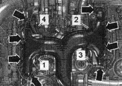
Tighten the bolts in 3 stages as follows.
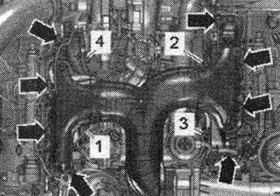
| Step | Screws | Tightening torque |
| 1 | "1...4", "arrows" | screw it in by hand until it stops |
| 2 | "1...4" | torque of 9 Nm in the specified, sequential. |
| 3 | "arrows" | torque of 9 Nm in any sequence. |
Removal and installation the intake manifold
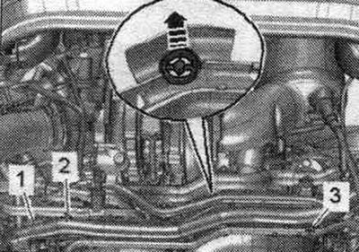
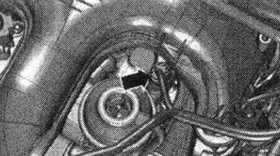
Remove the engine cover. Release the wiring harness and hoses using the lever "80-2000" on the wiring "1". Remove the coolant hose downwards "arrow". Unscrew the screws "2, 3" and remove the wiring "1".
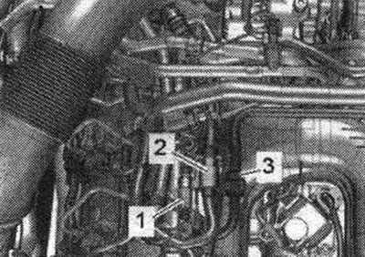
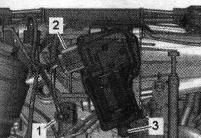
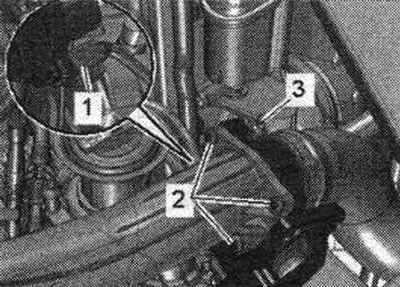
Unscrew bolts "1, 2" and remove the mounting clamp "3". Unscrew the union nuts "arrows" and remove the upper high-pressure line.
Release the plug connectors "1, 2" and the check valve "3" from the bracket.
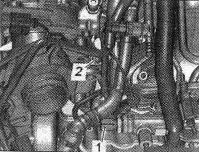
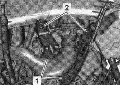
If present, unscrew bolt "2" on the high-pressure line mounting clamp. "Pos. 1" should not be taken into account.
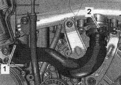
Unscrew bolt "1" on the intake manifold bracket on the right. "Pos. 2" should not be taken into account.
Disconnect plug "2" of the coolant valve of the cylinder head "N489" "pos. 1". Unscrew the bolts "arrows", put aside the bracket of the coolant valve of the cylinder head "M489".
Disconnect the "arrow" connector of the coolant temperature sensor "G62".
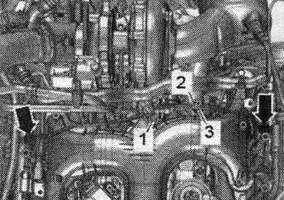
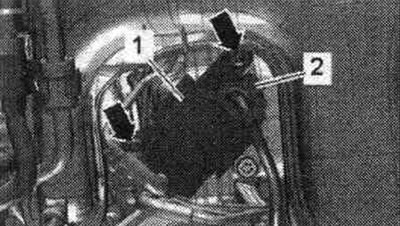
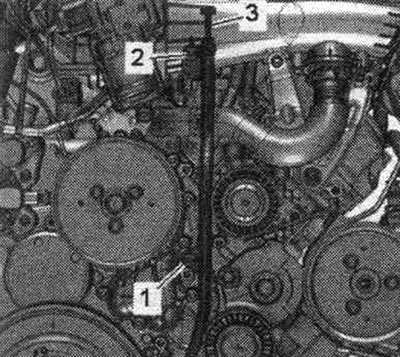
Disconnect electrical connectors "1, 2" and put the wiring harness aside on the left. Unscrew bolt "3" on the intake manifold bracket in the middle.
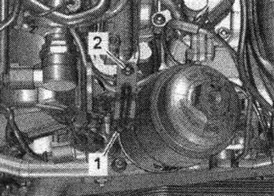
Remove plug "3". Unscrew bolt "2" of the oil dipstick guide tube. "Pos. 1" should not be taken into account.
Loosen screw clamp "2" of the system tube. eGR. "Pos. 1" should not be taken into account.
Unscrew bolts "2" of the left air duct bracket. "Pos. 1" should not be taken into account.
Disconnect connector "1" of the throttle control unit "J338". Loosen screw clamp "3" and remove the air duct hose. "Pos. 2" should not be taken into account.
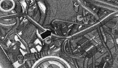
Disconnect the glow plug connectors. Remove the fuel pressure sensor "0247" arrow-.
Unscrew bolts "1...4" and "arrows" and remove the intake manifold.
Install
Installation in reverse order. Replace seals. Hose fittings, air tubes and hoses must be cleaned of oil and grease before installation. To secure all hose connections, use clamps of the appropriate series. To ensure reliable fastening of the air duct hoses to the fittings, the threaded connections of the already used clamps should be treated with a rust remover. Tighten the intake manifold bolts. Install the high pressure line. Install the dipstick guide tube. Install the system tube. exhaust gas recirculation.
[The article was copied from the website: AudiManual]