
High pressure pump
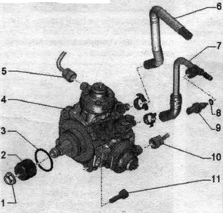
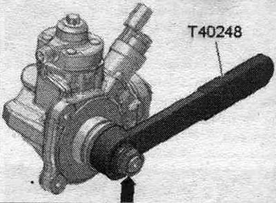
1. Nut: to unscrew, hold the adapter "pos. 2" with the support "T40248"; 70 Nm.
2. Fuel injection pump chain sprocket adapter; to unscrew the nut, hold "pos. 1" with support "T40248"; when replacing the fuel injection pump, transfer it to a new fuel injection pump.
3. Sealing ring: replace.
4. High pressure pump. Risk of fuel injection pump failure when running dry. Before starting the engine for the first time, the installed fuel injection pump must be filled with fuel.
5. High-pressure main; do not change the bent shape; check for damage before reinstalling; when replacing the fuel injection pump, the high-pressure line should also be replaced; lubricate the threads of the union nuts with clean oil; 25 Nm.
6. Fuel supply. hose.
7. Reverse fuel. hose.
8. Sealing ring: replace.
9. Fuel temperature sensor "G81": 2Hm.
10. High pressure line: do not change the bent shape; check for damage before reinstalling; when replacing the fuel injection pump, the high-pressure line should also be replaced; lubricate the threads of the union nuts with clean oil; 25 Nm.
11. Bolt: 22 Nm.
Take off
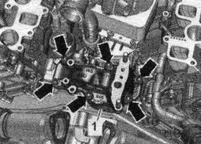
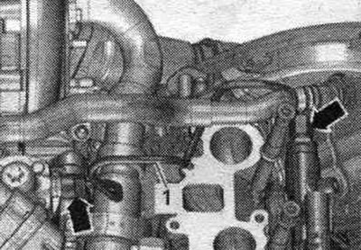
Remove the intake manifold. Remove the turbocharger. Remove the oil radiator. Remove the coolant shutoff valve. Unscrew the bolts "arrows" and move the turbocharger bracket "1" to the side.
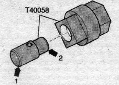
Remove rear noise insulation "1". Insert the guide pins of the adapter "T40058" as shown below: the large diameter "arrow 1" faces the engine, the small diameter "arrow 2" faces the adapter.
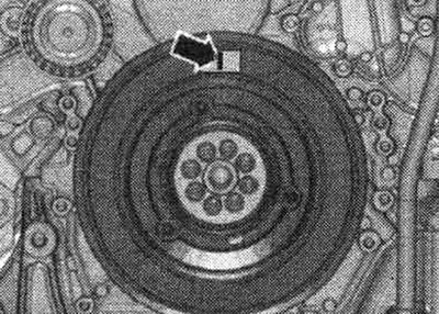
Risk of damage due to jumping of the camshaft drive chain. Rotate the crankshaft only in the direction of engine rotation "arrow". Turn the crankshaft with the adapter "T40058" to the "TDC" position.
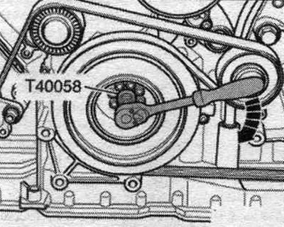
The "arrow" marking must be vertical to the center of the crankshaft, as shown in the figure.
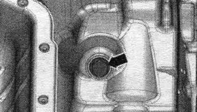
Unscrew the threaded plug "arrow" of the "OT" mark from the top of the oil. pallet.
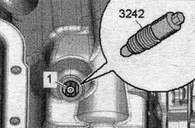
Screw the fixing bolt "3242" with a torque of 20 Nm into the hole, if necessary, slightly rotate the crankshaft -.1- in both directions to fully center the bolt.
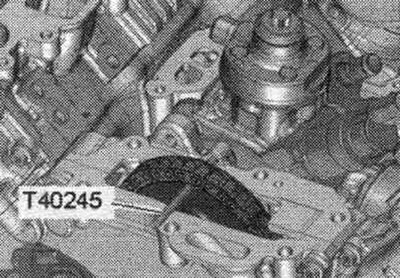
Secure the fuel injection pump chain sprocket with the locking pin "T40245".
Unscrew the union nuts "arrows" and remove the right high pressure line "1".
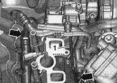
Unscrew the union nuts "arrows" and remove the left high-pressure line "1". Open lines and connections should be immediately sealed with a clean plug.
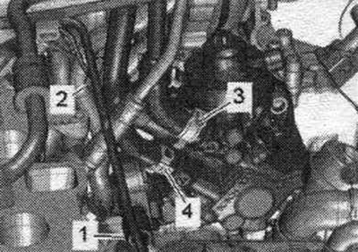
Disconnect plug connector "2". Remove the fuel hoses by loosening hose clamps "3 and 4". Ignore "Pos. 1".
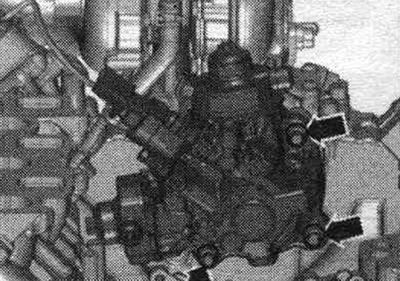
Unscrew the arrow screws and remove the fuel injection pump.
Install
Installation in reverse order. When replacing the fuel injection pump, the high-pressure lines should also be replaced. If the fuel injection pump is being replaced, transfer the adapter from the old pump to the new one. To loosen and tighten the arrow nuts, use the support "T40248".
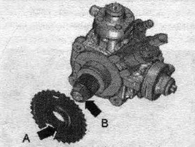
Insert the fuel injection pump into the chain sprocket. The double teeth "arrow A" on the chain sprocket must be aligned with the groove "arrow B" on the adapter on the injection pump shaft. Unscrew the locking bolt "3242" and the locking pin "T40245". Tighten the threaded plug of the "TDC" mark to the top of the oil well. pallet.
Install fuel. high-pressure lines. Install the coolant shut-off valve. Install the engine oil cooler. Install the turbocharger. Install the intake manifold. Install the rear noise insulation screen. Before starting the engine for the first time, the installed fuel injection pump must be filled with fuel.
This article was copied from an online resource AUDImanual.ru