
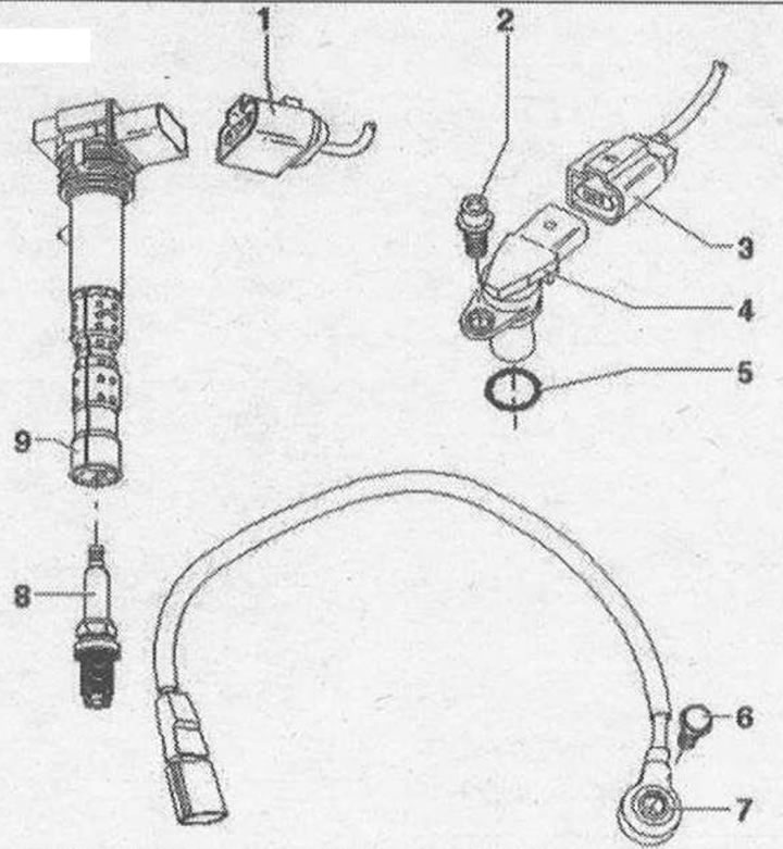
Ignition system 1. Ignition coil connector 4-pin; 2. Bolt, 10 Nm; 3.3-pin male connector; 4. Hall sensor: Hall sensor -G40- (cylinder bank 1); Hall sensor 3 -G300- (cylinder bank 1); Hall sensor 2 -G163- (cylinder bank 2); Hall sensor 4 -G301- (cylinder bank 2); 5. Seal ring. Replace if damaged. Lubricate with clean oil; 6. Bolt, 20 Nm; 7. Knock sensors. The contact surface between the knock sensor and the cylinder block must be free of corrosion, dirt and grease. Knock sensor 1 -G61- (cylinder bank 1). Knock sensor 2 -G66- (cylinder bank 1); 8. Spark plug. Remove and install using spark plug wrench -3122 V-, 30 Nm; 9. Ignition coil. Ignition coil 1 with output stage -N70-; Ignition coil 2 with output stage -N127-; Ignition coil 3 with output stage -N291-; Ignition coil 4 with output stage -N292-; Ignition coil 5 with output stage -N323-; Ignition coil 6 with output stage -N324-. To remove, use puller -T40039-
Removing the ignition coils
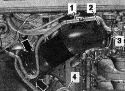
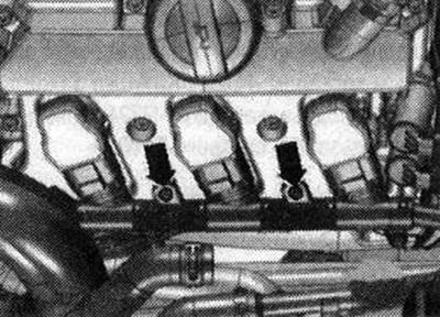
Removing the ignition coils of cylinder bank 1: For the ignition coil of cylinder 1 only: remove the lower part of the air housing. filter. For ignition coils of cylinders 2 and 3: remove air hose (Open hose clamp -3- Release clamps -arrows-).
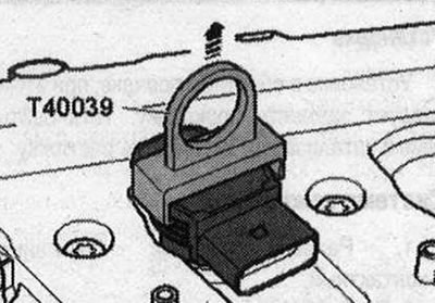
Remove the ignition coil wiring harness bolts. Unblock email connectors and remove them simultaneously from the ignition coils. Using a puller -T40039-, remove the ignition coils from the spark plug sockets.
Removing the ignition coils of cylinder bank 2: Unscrew the extension. coolant reservoir -arrows-. Disconnect plug connector for low coolant level warning switch -F66-bottom to extended. coolant tank and drain the expansion tank. reservoir with connected coolant hoses -1,2- and -3- to the side.
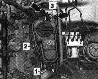
Unscrew bolts -arrows-.
Ignition system
Verification data
| Idle speed (not regulated) | |
| Ignition timing | Not installed, confirmed used |
| Ignition system | Ignition system with 8 separately located ignition coils (with integrated final stages), which are placed directly onto the spark plugs through a spark plug tip |
| Cylinder operating order | 1-5-3-6-2-4 |
Using a puller -T40039-, remove the ignition coil approximately 30 mm from the spark plug sockets. Unblock email connectors and remove them simultaneously from the ignition coils.
Installation
Easily insert all ignition coils into the spark plug sockets. Align the ignition coils with the connectors and simultaneously push all connectors onto the coils. Press the ignition coils evenly onto the spark plugs by hand (do not use percussion instruments). Install in reverse order. Electrical wiring of the ignition coils on the cylinder head casing: 5 Nm.
Visitor comments