
Table of contents: Left exhaust manifold. Tightening… ↓ Right exhaust manifold. Tightening… ↓ Heat shield for combined secondary… ↓ Removal the secondary air pump ↓ Installation ↓ Installation ↓
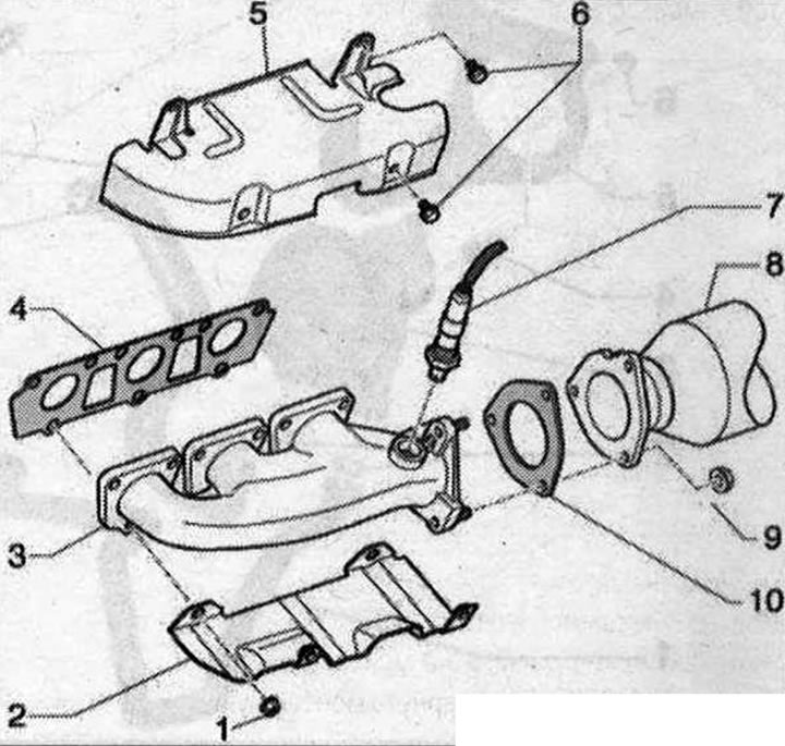
Exhaust manifold 1. Nut. Replace. Lubricate with heat-resistant paste; 2. Heat shield bracket; 3. Exhaust manifold; 4. Gasket. Replace; 5. Thermal insulation shield; 6. Bolt, 10 Nm; 7. Lambda probe before the catalytic converter. Cylinder bank 1 (right) lambda probe "G39", cylinder bank 2 (left) lambda probe 2 "G108"; 8. Catalyst. Protect from impacts and shocks; 9. Nut. Replace. Lubricate with heat-resistant paste. 23 N·m; 10. Gasket. Replace
Left exhaust manifold. Tightening sequence and torque
Tighten the nuts in the sequence "1...9" in 3 steps:
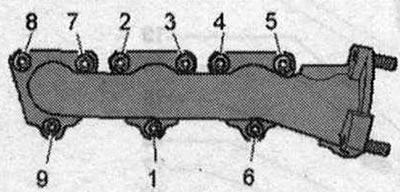
- 1. Tighten the bolts by hand until they stop
- 2. Pre-tighten to 15 Nm
- 3. Tighten to 25 Nm
Right exhaust manifold. Tightening sequence and torque
Tighten the nuts in the sequence "1...9" in 3 steps:
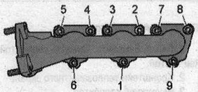
- 1. Tighten the bolts by hand until they stop;
- 2. Pre-tighten to 15 Nm;
- 3. Tighten to 25 Nm
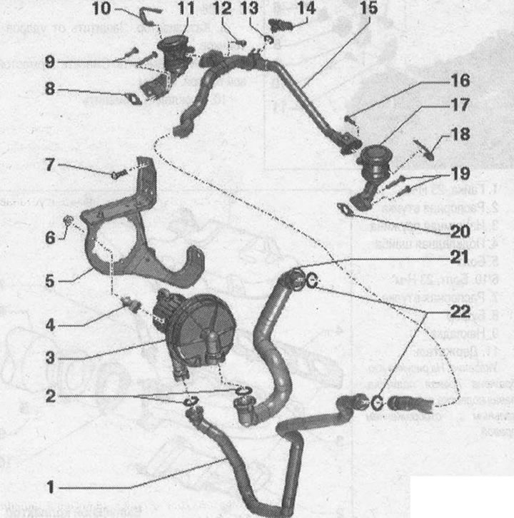
Secondary air supply system 1. Secondary air hose; 2. O-ring seal. Replace; 3. Electric motor of the secondary air supply fan "V101"; 4. Rubber-metal support; 5. Secondary air supply pump motor holder "V101"; 6. Nut, 9 Nm; 7/12/16. Bolt, 9 Nm; 8/20. Gasket. Replace; 9/19. Bolts, 9 Nm; 10. Vacuum hose (only cars in set for USA); 11. Right secondary air supply combination valve; 13. Sealing ring (only cars in set for USA). Replace; 14. Sensor 1 secondary air pressure "G609" (only cars in set for USA); 15. Pipe for secondary air; 17. Left combination valve for secondary air supply; 18. Vacuum hose (only cars in set for USA); 21. Secondary air hose; 22. O-ring seal. Replace
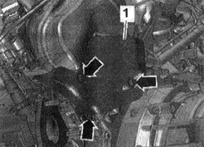
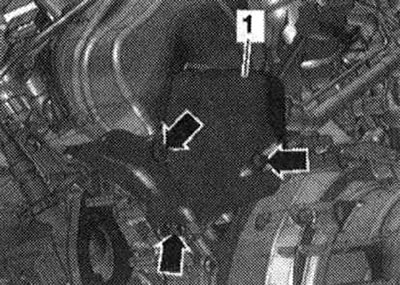
Heat shield for combined secondary air supply valve.
Tighten the heat shield "arrow" bolts "1" to a torque of 9 Nm.
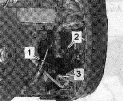
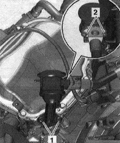
Removal the secondary air pump
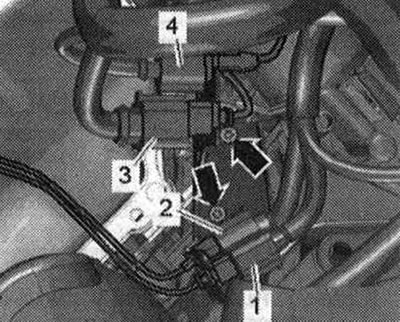
Remove the front noise insulation. Disconnect the electrical plug connection "3" of the secondary air pump motor "V101". Remove the secondary air supply hoses "1" and "2".
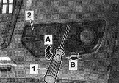
For better understanding, the installation position is shown with the wheel arch liner removed. Unlock the lock "arrow A" with a screwdriver "1". Disconnect the air intake grille "2" from the bumper cover "arrow B".
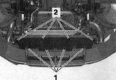
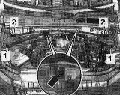
Unscrew bolts "1" and "2", remove the noise insulation screen of the bumper trim in the rear direction.
Unscrew the "arrow" bolts and remove the secondary air pump.
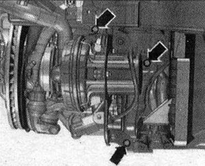
For better understanding, the installation position is shown with the power steering pump removed.
Installation
Installation is in reverse order, replacing the sealing rings. Install the front noise insulation screen. Install the noise insulation.
Removing the left secondary air supply combination valve
Remove the left front muffler. Remove the brace. Remove the plug connector "1" of the lambda probe 2 after the catalytic converter "G131" from the holder, disconnect and put aside.
Pos. "2,3,4" and "arrows" are not taken into account.
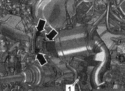
Unscrew the nuts "arrows" and bolt "1", remove the left catalytic converter from the exhaust manifold and place it at the back.
Loosen the bolts "arrows" and remove the heat shield "1".
Unscrew bolts "1" and "2" and remove the left secondary air supply combination valve.
Installation
Installation is in reverse order, replacing the gasket. Install the left catalytic converter. Install the tensioner.
Information obtained from this resource: AudiManual.ru