
Turbocharging elements
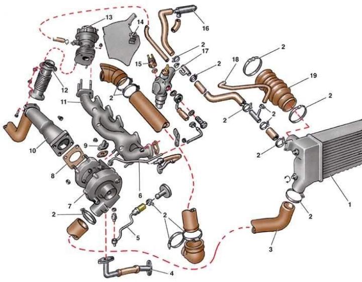
- 1 - Intercooler;
- 2 - screw clamp;
- 3 - air supply hose from compressor to cooler;
- 4 - oil drain line;
- 5 - pipe supplying coolant to the compressor;
- 6 - coolant drain pipe;
- 7 - turbocharger;
- 8 - gasket;
- 9 - oil supply pipe to the turbocharger;
- 10 - exhaust pipe;
- 11 - exhaust manifold;
- 12 - intermediate pipe;
- 13 - compressor shutdown regulator;
- 14 - thermal switch;
- 15 - cooling fan switch sensor;
- 16 - idle speed stabilizer valve;
- 17 - Engine cooling jacket pipe;
- 18 - hose from the cooler to the cylinder head;
- 19 - Air supply hose to the engine intake pipe
Execution order
1. Disconnect the wire from the negative terminal of the battery.
2. Loosen the clamps and remove the air supply hose to the engine intake pipe.
3. Loosen the clamps and remove the air duct (see Fig. Main elements of the fuel injection system).
4. Remove the air filter cover with the filter element (see pp. 1–2 of subsection 6.2).
5. Loosen the mounting bolts and remove the heat-insulating shield on the right engine mount bracket.
6. Loosen the nuts securing the muffler inlet pipe (see Fig. Turbocharging elements) to the turbocharger.
7. Loosen the fastening nuts and disconnect the intermediate pipe from the compressor shut-off regulator.
8. Disconnect the intake pipe from the bracket on the gearbox and remove it with the gasket.
9. Loosen the clamps and remove the hose supplying air to the generator.
10. Loosen the mounting nuts and remove the oil drain line.
11. On models with a liquid-cooled turbocharger, disconnect the coolant supply pipe to the compressor and the coolant drain pipe.
12. Remove the generator with the bracket (see subsection 12.1.3.1).
13. Loosen the mounting nuts and remove the turbocharger from the exhaust manifold.
14. Install the turbocharger in reverse order.