
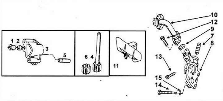
Oil pump parts
1 Drive unit for distributor (if it is installed)
2 Oil pump drive
3 Oil pump housing
4 Gear with shaft
5 Gate valve
6 Driven gear
7 Spring
8 Oil pump cover
9 Sealing ring
10 Oil suction pipe
11 Oil deflector
12 Bolt
13 Bolt M6x22
14 Bolt M8x90
15 Spring ring
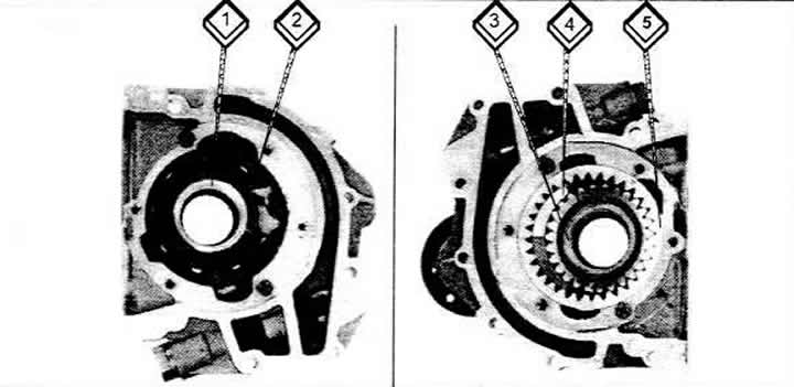
Oil pumps for five-cylinder engines
1 Inner rotor
2 Outer rotor
3, 5 Gears
4 Sickle.
Removal
Remove the oil pump.
Loosen the oil pump housing mounting bolts.
Pull the pump down until the shaft disengages and then pull it out completely.
If installed, also remove the ignition distributor, since it must be removed when installing the pump.
Installation
Installation is carried out in the reverse order of removal.
The pump is installed on the engine crankcase without a gasket. Tighten the bolts to 2Nm.
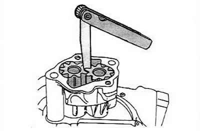
Before installing the distributor, use pliers to turn the oil pump drive shaft so that the journal surfaces lie parallel to the longitudinal axis of the crankshaft. Then insert the distributor or sleeve with the sealing ring (some models).
Check the ignition if the distributor is driven by the oil pump shaft.
Oil pump repair
Two gears in mesh and of the same size create pressure in the pump and transmit it from the inlet side to the discharge side. To maintain the correct pressure, the gears, of course, must not be worn beyond the permissible wear limit. Before simply installing a new oil pump, it is necessary to check the internal parts of the pump.
Remove the two short bolts from the pump cover.
Remove the cover together with the oil suction tube.
Remove the drive shaft with the gear and the "weak" gear from the housing.
Remove both strainer bolts from the pump cover and remove the O-ring in the middle of the tube. Clean all parts thoroughly before checking.
Check the oil pump housing for bending. When the bearing points wear out, pressure losses occur, so it may be necessary to replace the housing.
Check the gears for wear by inserting a flat feeler gauge between the teeth to measure the lateral clearance. It should be 0.05 - 0.2 mm (wear limit is 0.2 mm). If it is greater than this value, then the gears need to be replaced. In this case, you may have to replace the pump completely.
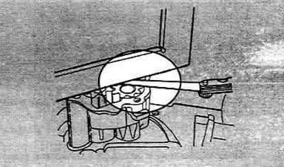
The axial clearance of the gears should be within 0.06 - 0.15 mm (wear limit is 0.15 mm). To measure the clearance, apply a steel angle or steel ruler to the upper surface of the pump body and check the gap between the ruler and the surface of the gears using a steel flat feeler gauge.
Check the tightness of the driven gear shaft fit in the pump housing. If necessary, re-tighten the shaft by rivet-peening the shaft end again. If this fails, replace the pump housing.
Always replace gears in pairs if signs of wear or damage to teeth are detected. Wear is mainly visible in cut areas.
When assembling the oil pump, make sure that the surfaces between the two parts of the housing are clean. Lubricate all parts with oil before assembly. Make sure that the gears are lubricated with oil, as they can be damaged during the first start-up and dry running. Check that the gears rotate without jamming or interference before installing the pump.
The original text of the material can be found on the website: AUDIMANUAL.ru