
Table of contents: Monotronic ↓ Checking the ignition transformer ↓
Monotronic
This part combines the switch and the powerful final stage of the transistor ignition with the ignition coil: the combination in one housing prevents voltage losses.
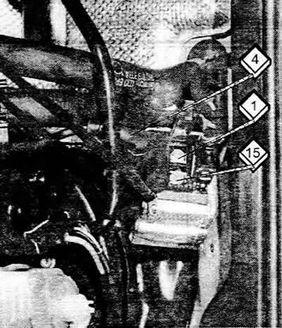
The black wire from the mounting block to the ignition transformer is used to supply voltage to the primary winding part of the ignition coil. The connection to the primary winding is made via the terminal contact (15) during the so-called closing time
In order for the necessary ignition energy to be available throughout the entire operating area, the time for supplying current to a part of the ignition coil is selected in accordance with the number of revolutions and the supply voltage. In addition, the switching (commuting) part can limit the primary winding current to the ignition coil part to the maximum value.
To protect part of the ignition coil, the ignition transformer has a safety shutdown system. Since the current circuit is always closed when the ignition is turned on, the coil windings can overheat when the ignition remains on for a long time. This is prevented by a safe shutdown: 12 V is applied to terminal (15), and on terminal (1), on the contrary, a maximum of 10 V (or less). Thus, the winding "consumes" at least 2 V, which can cause them to overheat. However, after 1-2 seconds, the ignition transformer also approaches terminal (1) 12 V. There will be no more voltage difference in the windings and the consumer switches off in a peculiar way.
The interrupt pulse is fed through the ignition/injection control unit via the green/black wire to the switching part with the final stage of the ignition transformer. There, the Hall sensor pulse is processed and amplified, which, as indicated above, controls the current through the primary winding via the contact of terminal 1.
High voltage, approximately 35,000 V, comes out of the thick terminal (4) of the transformer and passes through the high-voltage wire of the distributor cap.
The brown wire makes the connection to ground.
Checking the ignition transformer
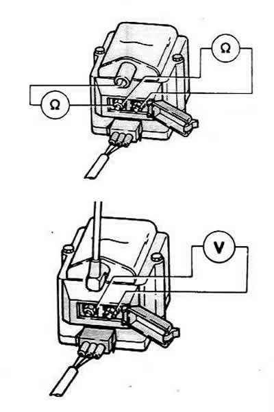
The figures show how to connect the devices to test the ignition transformer.
Visual inspection is described above.
To check the resistance, remove the three-pin plug and the high-voltage wire on the transformer with the ignition off. The primary and secondary windings of the ignition coil are measured.
Using an ohmmeter, measure the resistance between the transformer terminals 1/- and 15/+.
Nominal value: 0.5-0.7 Ohm.
The next measurement is carried out between terminals (15) and (4).
Nominal value 3-4 kOhm.
If the measured values do not match the specified values, replace the transformer.
It is impossible to detect a short circuit between windings using these measurements. If the transformer is suspected despite satisfactory measurement results, the removed transformer should be checked in a workshop.
To check the voltage, you need a voltmeter with wires with sharp tips.
Connect the voltmeter to the external contacts of the three-pin plug of the ignition transformer.
Turn on the ignition: the voltmeter should show about 12 V. If there is no voltage, then you need to look for a break in the positive or "ground" wires.
Turn off the ignition.
Using auxiliary wires with sharp tips, connect the LED voltage tester to contacts (2) and (3) of the ignition transformer plug.
The assistant must turn on the starter.
The LED should blink. If it does not, then either the Hall sensor or the control unit is faulty.
Turn off the ignition.
Safe shutdown: Put the 3-pin plug back onto the transformer.
Connect the voltmeter to the contacts of terminals (1) and (15) of the transformer.
Turn on the ignition. The voltage should be at least 2 V (voltage difference between windings).
After 1-2 seconds the voltage drops to zero.
If this is not the case, then the transformer's safe shutdown is faulty and the system must be replaced.