
Table of contents: KE-Motronic ↓ Checked the ignition coils ↓
KE-Motronic
The primary current is supplied to terminal 15 of the coil.
Through the primary winding of the ignition coil, voltage from its terminal 1/- is supplied to the commutator. A tachometer is also connected to terminal (1).
A high voltage of approximately 25,000 V comes from the middle terminal 4 of the coil through the high voltage wire to the distributor cap.
The ignition coils for the engines in question differ in their technical data - do not confuse them! The coils are distinguished by the green and gray stickers. In combination with the KE-Motronic system, another version of the ignition coil is installed.
Checked the ignition coils
Visual inspection of the coil was described above.
To check the resistance, remove all wires from the ignition coil with the ignition off. The primary and secondary windings of the coil are measured.
Using an accurate ohmmeter, measure the resistance between terminals 1/- and 15/+ of the ignition coil.
Nominal values:
- Coils with green sticker: 0.52-0.76 Ohm.
- All other coils: 0.6-0.8 Ohm.
The following measurements are made between terminals 1 and 4.
Nominal values:
- Coils with gray sticker: 6.0-8.5 kOhm.
- Coils with green sticker: 2.4-3.5 kOhm.
- KE-Motronic: 6.5-3.5 kOhm.
If these values are not achieved, replace the ignition coil.
With these measurements it is impossible to determine a short circuit between the windings. If suspicion falls on the ignition coil despite the correct measurement results, the coil should be checked in a workshop.
To check the voltage, you need to have a charged battery.
Connect a voltmeter between terminal 15 of the ignition coil and ground.
Turn on the ignition.
The voltage must be at least 11.5 V.
Make the same measurement on the black wire of the switch.
If there is no voltage at all or it is too low, then the fault is in the wire to the ignition switch.
The wire plugs on top of the ignition coil have the following designations:
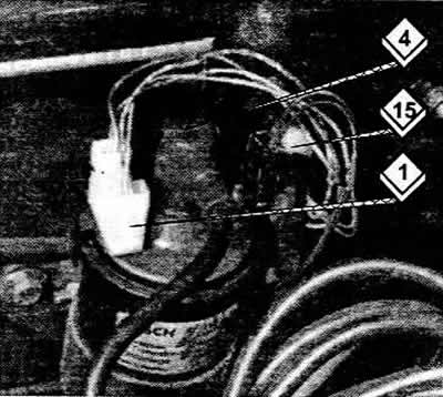
1 Interrupt pulse from the switch.
4 High voltage.
15 Voltage supplied from the clamping switch.
Information obtained from this resource AUDImanual