
Remove the wire to the intake manifold heater and, if available, to the automatic starting device.
Remove the covering from the gutter.
Remove the rubber cuff from the multi-pin plug of the switch.
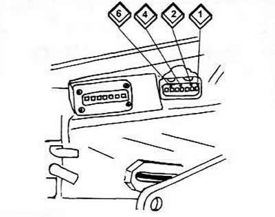
Power supply: After releasing the locking clips, remove the plug.
Connect the voltmeter to contacts 2 (brown wire) and 4 (black wire).
Turn on the ignition. The voltage should be about 12 V.
If there is no voltage, then you should look for a break in the electrical equipment diagram.
Turn off the ignition, put the plug on the switch.
Safe disconnection: connect a voltmeter between terminal 1 and ground.
Immediately after turning on the ignition, the voltage should be about 6.6 V.
After 1-2 seconds, the voltage increases to about 12 V. This is a safe shutdown so that the ignition coil cannot overheat if the ignition is on for a long time.
If there is 12 V immediately at terminal 1, remove the plug from the switch again.
Check the continuity of the following wires: terminal 1 (green), terminal 15 (black), ground (brown).
If no fault is found, then the switch needs to be replaced.
Since the ignition coil may melt due to the failure of the emergency shutdown, it is necessary to check for the protrusion of the filling mass. If so, replace the ignition coil.
Pulse processing: disable (neutralize) ignition.
Connect a voltmeter between terminal 1 of the ignition coil and ground.
Remove the three-pin plug on the ignition distributor.
Insert a needle, cotter pin, etc. into the middle contact.
Turn on the ignition, the voltmeter should show 12 V after 1-2 seconds.
Touch the extended middle contact to the ground and observe the voltmeter.
In 1-3 seconds the voltage will drop by about 6 V and then rise again to about 12 V.
If the voltage remains at 12 V, the switch is faulty.
If the voltage drops briefly, but there are no sparks, then the ignition coil is faulty or the high-voltage wire between the coil and the distributor is damaged.
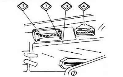
The switch of a car with mechanical ignition timing adjustment of the system is usually located on the radiator for cooling (3), which serves to remove heat. Here the multi-contact plug (4) is removed so that the contacts (1-7) on the switch are visible.
The original text is available on the website: Audimanual.ru