
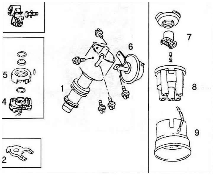
Ignition distributor parts
1 Distributor body
2 fastening clamp
3 Plug connection
4 Hall's Armor
5 Rotor with hood
6 Vacuum chamber (only with mechanical installation of opera married ignition)
7 Distributor rotor
8 Distributor cover
9 Metal protective cover (screen) to suppress radio interference.
Power supply: remove the 3-pin plug on the ignition distributor.
- Connect a voltmeter between the outer contacts of the plug with red/black and brown/white wires.
- Turn on the ignition. The voltage must be at least 10 V.
- If there is no voltage, then there is a break in the wires or a defect in the switch or control unit.
Opening impulse: Remove the plug from the cold start valve and from the injection unit or from the injector cable holder.
- Slide back the protective sleeve on the multi-pin plug of the Hall sensor on the distributor. The plug itself remains connected.
- Voltmeter or LED voltage probe (not an ordinary test lamp) connect between the middle pin and one of the outer pins.
- Have an assistant turn the engine over with the starter.
- The LED should flash.
- If this is not the case, then the Hall sensor is defective.
Checking the Hall sensor of the KE-Motronic system
Remove the plug by pressing the brackets.
Connect a diode voltage probe with suitable tips between the green and brown wires.
Turn on the ignition, crank the engine by hand or starter.
When cranking the engine, the LED should alternately light up and go out.
If it's not. switch off the ignition and check the voltage supply to the Hall sensor and the KE-Motronic control unit.
Remove the 3-pin plug on the ignition distributor.
Connect a voltmeter between the outer pins of the plug with red/black and brown/white wires.
Turn on the ignition. The voltage must be at least 9 V.
Slide the rubber bushing back on the plug of the Hall sensor, put the plug back on.
Connect a diode voltage tester with suitable auxiliary wires between the middle pin on the plug of the Hall sensor and the plastic terminal of the battery.
Turn on the ignition, crank the engine by hand or with a starter.
If now the diode alternately flashes and goes out, then the Hall sensor is in order.
If it does not light up, then the cause is in the Hall sensor and / or in the KE-Motronic control unit.
There are no verification methods in the usual sense of the word for the control unit.
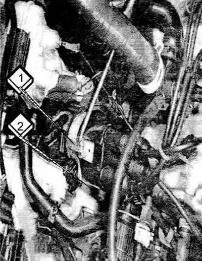
Opening the distributor
Use a screwdriver to pry out both retaining clips (1) distributor caps. Bolt below (2) distributor clamp.
Remove the ground wire of the existing protective cover made of metal.
Remove the distributor cap, leaving the high voltage wire connected.
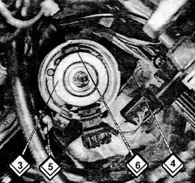
Distributor with cap removed
1 Rotor with hood
4 3-pin plug
5 Vacuum chamber for mechanical ignition timing
6 hall sensor
Remove the distributor rotor and the dust cover underneath.
When installing the dust cover, position it as follows. so that the protrusion of its fastening enters the recess on the edge of the distributor housing.
The distributor rotor has a protrusion that fits into a recess in the distributor shaft.
The distributor cap also features a molded «spout», which is included in the recess in the distributor housing.
Engines with power over 100 kW: for models with a 20-valve engine, the distributor rotor cannot be removed - it is glued to the shaft.
If the distributor rotor needs to be replaced, it must be decomposed.
This is done by crushing with pliers. Do not break under any circumstances, otherwise the distributor shaft or its bearings may be damaged (bearings).
Checking the ignition distributor
Remove distributor cap. It must be clean inside and out, so that current jumpers from dirt, moisture, etc. do not form.
The contact coal in the middle should be smooth and shiny, slightly springy and move without jamming.
The distributor rotor must not be oily on its contact surfaces, including on the interference suppression resistance.
Distributor rotor resistance (designation R1) should be 0.6-1.4 k ohm.
The dark streaks on the distributor cap are burn marks from leakage currents that pass through dirt or damp places.
In extreme cases, places can be scratched out with a screwdriver or a knife, and then covered with glue, varnish, etc.
Attention. Due to high voltages, there may be interruptions between the high voltage wires and the round metal cover. In this case, you can remove this protective cover completely.
Removing the distributor
Set the first cylinder to the point corresponding to the ignition timing.
Remove distributor cap.
On some engines, it is necessary to unscrew the bolt on the distributor mounting clamp, pull the distributor up.
On others, unscrew the two mounting bolts on the base of the distributor, remove the distributor. To install the distributor, it is necessary to put the engine in the following positions.
Label «0» flywheel should be opposite the arrow in the inspection hole.
In addition, in the hole for the ignition distributor, the pin of the oil pump shaft drive must be parallel to the crankshaft.
The mark made with a punch on the reverse side of the camshaft drive gear must be at the height of the seal (gaskets) cylinder head covers.
Rotate the distributor shaft so that the distributor rotor points to the mark on the edge of the distributor housing. Insert distributor.
Engine power over 100kW: The distributor drive coupling is asymmetrically shaped so that the distributor can only be inserted in one correct position.
Finally, adjust the ignition.
Visitor comments