
Table of contents: Removal ↓ Measuring cylinder bores ↓ Checking pistons and connecting rods ↓ Assembly of pistons and connecting… ↓ Installation of pistons and… ↓
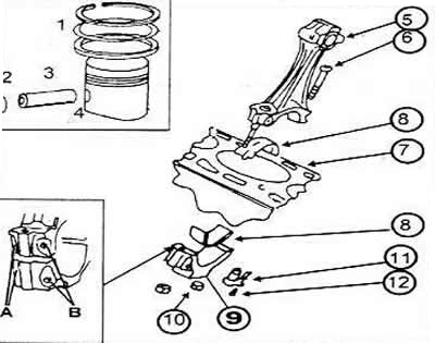
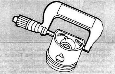
Piston and connecting rod assembly diagram
1 Piston ring
2 Piston pin retaining ring
3 Piston pin
4 Piston
5 Connecting rod
6 Connecting rod bolt
7 Cylinder block
8 Connecting rod bearing shell
9 Connecting rod bearing cap.
10 Connecting rod bearing cap nut
11 Oil jet
12 Pressure relief valve, opens at 2.5-3.2 bar. The letters indicate the designations of the connecting rod and cover (A) and the location of the cast projections (B). The latter should be facing the pulley
The pistons and connecting rods are knocked upward from the inside of the cylinder block using the handle of a hammer after removing the connecting rod bearing caps and bearing shells. When performing this work, the following instructions regarding the designations and installation positions of the parts, as well as the features of the various engines, must be followed. The instructions apply to all engine types.
Removal
Each piston and its connecting rod should be marked with the number of the cylinder from which it was removed. It is best to paint this number on the bottom of the cylinder. In addition, an arrow should be painted on the bottom of the cylinder pointing to the front of the engine.
When removing pistons with connecting rods, the exact position of the connecting rod bearing caps should be marked and immediately after removing the connecting rod and bearing cap, the cylinder number should be applied to one side. This is best done with a center punch (for cylinder No.1 - one blow with a center punch, etc.).
The connecting rod and connecting rod bearing cap must be assembled so that the cast projections are opposite each other. Both cast projections must face the crankshaft pulley after the connecting rod is installed.
Some petrol and diesel engines have oil jets to cool the pistons. They are located at the bottom of the cylinder bores.
Mark the position of the bearing shells according to the connecting rod numbers and their position relative to the bearing caps. Also mark the upper and lower shells with paint on the back side.
When ordering new pistons, be sure to specify the model and year of manufacture. Pistons are manufactured to the appropriate compression ratio and have different recess depths.
When removing the pistons and disconnecting them from the connecting rods, proceed as follows:
Remove the bearing caps and liners by knocking out the parts in the manner specified. If necessary, scrape the ring from oil deposits at the top of the cylinder bore using a scraper.
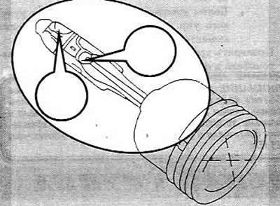
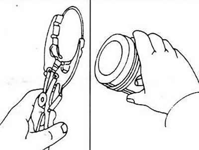
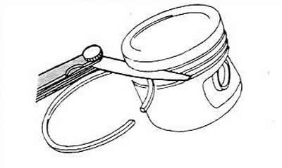
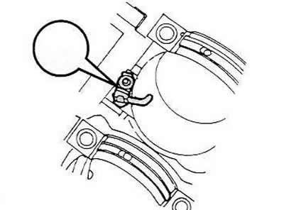
Press out the piston pin after removing the retaining ring. The cutout in the piston pin hole allows the use of a pointed tool for removal, so that the retaining ring can be pried out as shown in the figure. The pin should be pressed out using a suitable punch (mandrel).
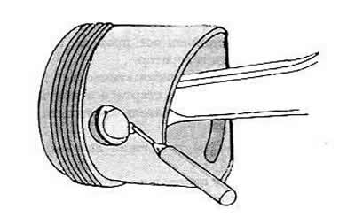
Remove the piston rings one by one using a piston ring puller. If the rings are to be reinstalled, they must be marked accordingly. Piston rings are very fragile, which means that when removing them, even with a puller, you must be very careful not to open them too much.
If you don't have a piston ring puller, you can slide metal strips evenly under the ring in different places on the piston. One strip must be under the ring lock to avoid scratches.
After removing the piston ring, it should be inspected immediately. Both upper rings are marked on one side with the word "TOP" or the word "OBEN". This side should be on top after installing the ring. The third ring can be installed with either side.
Measuring cylinder bores
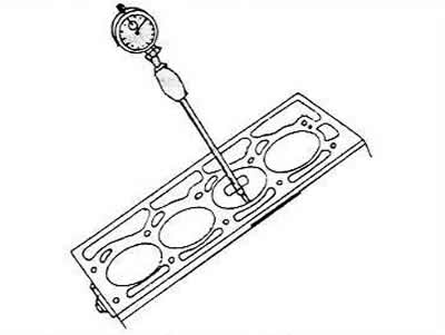
To measure the cylinder bores, you need to use a special pointer gauge, which can be used to measure the upper, middle and lower parts of the bore. If you do not have a pointer gauge, this operation cannot be performed.
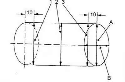
The cylinder bore measurements should be taken in the directions "A" and "B". In addition, measurements should be taken at a distance of 10 mm from the top edge, 10 mm from the bottom edge and in the middle part, i.e. at levels 1, 2 and 3. In total, six measurements should be taken for each cylinder bore. All measured values should be recorded and compared with those given in the tables of dimensions and adjustment parameters.
It should be borne in mind that all cylinders will have to be bored, even if the dimensions of one of the cylinders are not within the norm. A deviation of 0.08 mm from the nominal value is permissible. The repair dimensions of the pistons are indicated in the tables of dimensions and adjustment parameters.
The final cylinder bore size is determined by measuring the piston diameter, which is taken 10 mm from the bottom edge of the piston skirt and in the right corner of the piston pin bore.
To this dimension, add the piston clearance of 0.03 mm. In addition, allow for an additional 0.02 mm for honing the cylinder. To check the piston clearance in the cylinder bore, measure the piston and the cylinder bore as described above and calculate the difference between these values. If the result exceeds 0.08 mm, the cylinders must be bored, since the clearance has reached the wear limit.
Checking pistons and connecting rods
All parts should be carefully checked. If parts show signs of grooves, gouges or wear, they should be replaced. The following checks should be made for pistons:
Measure the piston ring clearances in the grooves by height, installing the rings in turn in the corresponding grooves. The clearance between the ring surface and the piston groove surface is determined using a flat feeler gauge. If the ring clearance exceeds 0.12 mm, then either the rings or the pistons are worn. The nominal value is 0.02-0.07 mm.
Insert all piston rings from the bottom of the cylinder block into the cylinder bores in order. Using an inverted piston, the rings should be pressed down approximately 15 mm. At the same time, both ring taps should be moved to measure the gap in the ring lock.
The nominal values are given in the tables of dimensions and adjustment parameters. The wear limit is different for different piston rings.
If the gap is too small (for example, if the ring is new), the edges of the ring should be filed down. To do this, clamp the file in a vice. If the gap in the ring lock is too large, the corresponding ring should be replaced.
Piston pins and connecting rod bushings should be checked for wear and abrasion. If even one connecting rod is defective, the entire set should be replaced.
Connecting rod bearing nuts must be replaced every time.
The connecting rods should be checked for bending and twisting in a special device.
Check the connecting rod bolts for damage and replace if necessary. In this case, tension bolts are used and they should only be replaced with the same ones.
Assembly of pistons and connecting rods
If the piston cooling jet was removed, it should be screwed in together with the safety valve (27 Nm). The jets are located at the bottom of the cylinder holes.
If pistons are replaced, check that all pistons are the same type.
Heat the pistons to 60°C (put in hot water). It is important to have a suitable tool that can be applied to the inside of the piston pin.
Press your fingers into the heated pistons and connecting rods with your hand.
When assembling pistons and connecting rods, the following instructions must be followed:
Arrow on the piston bottom (or painted or stamped on the new piston) must face the front of the engine.
The cast projections on the connecting rod and bearing cap must face the pulley. The cylinder number markings on the connecting rods and bearing caps must match.
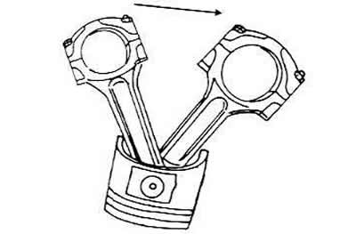
Check that after assembly the piston can swing freely on the connecting rod if moved in the direction of the arrow.
Using piston ring pliers, install the rings into the grooves one by one. Both compression rings can be mixed up, so it is necessary to check their cross-section before installation. In addition, both compression rings are marked on one side with the word "TOP" or "OVEN" and this designation should be read from above after installation of the ring.
Install the three-piece oil scraper ring, distributing the locks evenly
Installation of pistons and connecting rods
Lubricate the cylinder bores well.
Lay out all connecting rods according to cylinder numbers. The cast projections on the connecting rods and bearing caps must face the crankshaft pulley.
The arrows on the piston crowns should point towards the front of the engine.
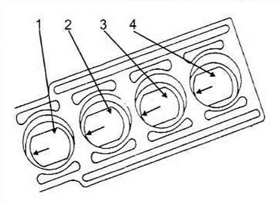
Position the piston ring locks at the same distance around the piston circumference, i.e. every 120°. The piston and connecting rod assembly diagram shows how the locks should be positioned in relation to the piston pin.
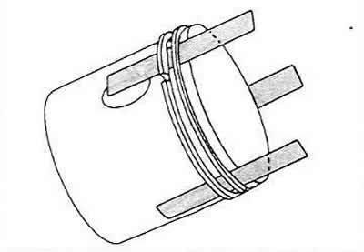
Position the piston ring tension band as shown in the figure and press the piston rings into the grooves. Check that they are pressed in well.
Place short pieces of rubber or plastic tubing over the connecting rod studs to avoid scratching the cylinder bore.
Turn the crankshaft so that the two journals of the shaft are in the bottom dead center position.
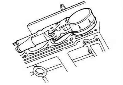
Push the connecting rod into the hole from above. To do this, the engine must be laid on its side so that the connecting rods can be brought to the bearing journals without scratching the cylinder bores or the connecting rod journals. The connecting rod bearing shell should already be in the connecting rod, with the protrusion in the recess.
Push the piston in until the rings are pushed into the cylinder bore one by one, and the base of the connecting rod should sit on the crankshaft journal. Be careful not to scratch the bearing journal.
Place the second bearing shell into the bearing cap, lubricate the shell well, press the cap onto the connecting rod studs and hammer it in lightly. The rubber tube sections must first be removed. Be sure to pay attention to the fact that the cast projections on the connecting rod and the connecting rod bearing cap match, otherwise you can make a mistake at the last moment
Lubricate the mating surfaces of the nuts on the connecting rod bearing caps with oil. Tighten the connecting rod bearing cap nuts alternately to a torque of 30 Nm and from this position tighten another 90°, i.e. a quarter of a turn.
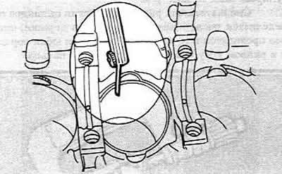
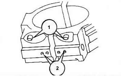
After screwing on the connecting rod bearings, each bearing should be inspected again. Experience shows that defects in connecting rod bearings sometimes appear after repairs have been completed, when the bearing cap and connecting rod are not screwed on perfectly. The number (1) in the figure indicates both of the above-mentioned cast projections, and the number (2) indicates the connecting rod bearing cap and connecting rod, in this case for the second cylinder. These marks should be located opposite each other on all connecting rods. Such an inspection must be carried out before closing the engine crankcase.
After installing the connecting rods, the crankshaft should be turned several times to determine if there is any jamming. If there is, you need to check again whether the pistons are in the correct position, i.e. the arrows on the bottoms should be facing forward (towards the pulley).
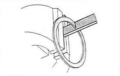
Using a feeler gauge, check the clearance between the side surface of the connecting rod and the surface of the crankshaft.
In this case, you should press the connecting rod bearing to the right, as shown in the figure, so that there is a gap for inserting the measuring probe. This is the axial clearance of the connecting rod bearing, and it should not exceed 0.37 mm.
Install the oil pan.