
Table of contents: Removal the crankshaft ↓ Checking the crankshaft parts ↓ Installing the crankshaft ↓
Crankshafts vary between engine types because they have different piston strokes. If a partial engine is installed, it comes with a needle bearing for the clutch shaft. This should be removed if the engine is designed to work with an automatic transmission.
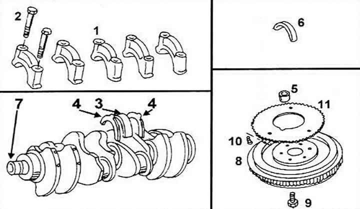
Crankshaft mounting from the bottom
1 Main bearing cap
2 Cover bolts, 63 Nm
3 Lower bearing shell, white oil channel
4 Half adjusting washer
5 Needle bearing (only with manual transmission)
6 Lower bearing shell without oil channel
7 Crankshaft
8 Flywheel
9 Flywheel bolt (tightening torque is specified in the text)
10 Bolt, 10 Nm+90°
11 Toothed gear for engine speed control
Removal the crankshaft
To remove the crankshaft, you need to remove the engine.
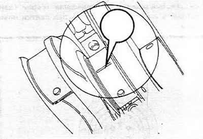
On a car with a manual transmission, hold the flywheel ring gear with a screwdriver and unscrew the flywheel bolts. The bolts can also be loosened with a spanner without holding the flywheel. To do this, place the spanner in the right corner and hit the edge of the spanner with your hand. The impact will loosen the bolts in most cases. To hold the flywheel, you can drill two holes in a flat piece of metal and screw it to the flywheel in the specified place. Hold the engine and loosen the bolts. First, remove the clutch. Mark its position relative to the flywheel. On the inside of the flywheel there is a toothed ring for "determining" the engine speed. and it must not be damaged when removing the flywheel.
When tightening the bolts, the strip should be screwed on from the other side.
Please note: The engine may be equipped with a conventional flywheel or a dual flywheel (double mass). The tightening torque of the mounting bolts is different for them.
From the front of the engine, loosen the crankshaft pulley bolts (torsional vibration damper), holding the flywheel.
On vehicles with an automatic transmission, the drive plate should be unscrewed in the manner described above.
Remove the cylinder head together with the intake and exhaust manifolds. Some parts are removed when the engine is removed (depending on its type).
Unscrew the pulley from the coolant pump and the lower timing belt cover.
Mark the direction of rotation of the toothed belt with paint on the outside.
After loosening the belt tension nut, remove the toothed belt from the drive gears and tensioner. The camshaft must not be turned after this.
Unscrew the oil pan.
Remove the oil pump.
If you only need to remove the crankshaft, the pistons and connecting rods can be left in the cylinder block. Otherwise, you need to remove the pistons and connecting rods. If the pistons and connecting rods remain in the block, you should mark the connecting rod bearing caps in order, remove them and store them together with the bearing shells. Do not forget that damaged tension bolts must be replaced.
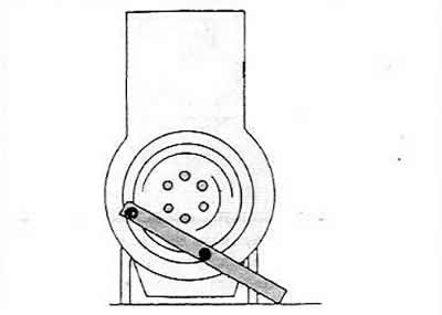
Mount the dial gauge on a stand in front of the front of the cylinder block or attach it with a magnetic mount to the cylinder block as shown in the figure, placing the dial gauge against the crankshaft. Using a screwdriver, push the crankshaft in one direction, set the dial gauge to zero and push the shaft in the other direction. The dial gauge will indicate the axial clearance of the crankshaft and this value should be recorded. If it exceeds 0.25 mm, this should be taken into account during assembly. The center bearing shells are equipped with adjusting washers to compensate for large axial clearance.
If a pointer gauge is not available, the clearance can be measured on the middle bearing between the bearing flange and the crankshaft surface using a feeler gauge. When sliding the feeler gauge in (thickness not more than 0.25 mm), the shaft should be pressed in one direction.
Loosen the bolts securing the sealing flange on the front side of the engine and remove the flange with the gasket.
Remove the engine intermediate plate, unscrew the bolts of the seal flange and remove the flange with the seal. The intermediate plate is guided by guide bushings.
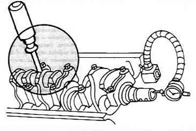
Loosen the crankshaft bearing cap bolts gradually and remove them one by one. Make sure the cap numbers are clearly visible. Cap #1 is located on the pulley side.
Remove the bearing shells from the journals and store them with the corresponding bearing caps. Note that some shells have lubrication grooves and others do not.
Carefully remove the crankshaft from the engine crankcase.
Remove the remaining liners from the crankcase and store them with the other liners and bearing caps. These liners are provided with lubrication channels and must be reinstalled in the crankcase during assembly. Remove the lower halves of the adjusting washers on the middle bearing. The washers should be marked on the side.
Checking the crankshaft parts
Carefully inspect the crankshaft for damage and take precise measurements of the main and connecting rod bearing journals. The main bearing journals and connecting rod journals can be bored up to three times, so that a shaft with oversize (smaller) bearing shells can be installed. The diameter of the connecting rod journals is the same for all engine types.
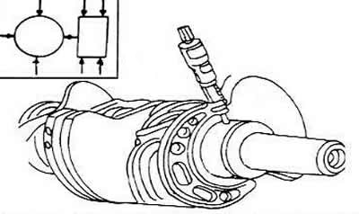
Clamp the crankshaft between lathe centers (or place the necks of the outer bearings in the prisms) and measure the runout on the middle journal using a dial indicator. The runout should not exceed 0.06 mm. Otherwise, the shaft should be replaced.
Measure the clearances in the main and connecting rod bearings:
- Clean the bearing shells thoroughly and place them in the bearing holes of the cylinder block or in the connecting rods.
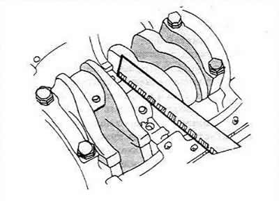
- Put a piece of material on each "Plastigage" (plastic "wire") on the journal of each main bearing and on the cap of each main bearing with inserted liners. Tighten the bolts with a tightening torque of 65 Nm. Do not turn the shaft after this
- To check the clearances of the connecting rod bearings, you need to put the connecting rod to the crank journal and put a piece "Plastigage" on the upper part of the connecting rod journal (arrow). Install the bearing cap with the liner and tighten the nuts to a tightening torque of 3 Nm. Since the shaft cannot be turned any further, measurements are taken on two connecting rod bearings located at the bottom dead center.
- Unscrew the caps on the main bearings. On the connecting rod bearings, unscrew both caps in turn.
- Using the measuring ruler included in the kit "Plastigage" measure the crushed strips of material at the widest point. If this value exceeds 0.17 mm for main bearings or 0.12 mm for connecting rod bearings, the bearing caps must be replaced with new ones, and it must be taken into account whether the journals were previously reground.
- To check the clearances of the remaining connecting rod bearings, you need to turn the crankshaft and take measurements on the other two connecting rod bearings as described above. If there is no set "Plastigage", but you know how to use a depth gauge, you can measure the clearances of the main and connecting rod bearings using the method described below.
Install the bearing caps with inserted liners according to the bearing numbers on the cylinder block and tighten the bolts with a tightening torque of 65 Nm. It is imperative to pay attention to the fact that the liners get into the previous bearing holes. If the clearances of the connecting rod bearings are measured, it is necessary to insert the liners into the connecting rods and into the caps, screw the caps with the same nuts, tightening them with a torque of 30 Nm.
Measure the inner diameters of the bearings. In doing so, observe the direction of measurements (A) and (B) and the locations of measurements (1) and (2). In doing so, you can determine the difference from the circle (A and B) and the amount of narrowing (1 and 2). Record the results obtained for each bearing.
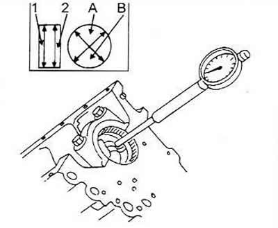
Measure the diameters of all bearing journals in order using a micrometer. Again, measurements should be taken at specific locations, which are indicated by arrows. Record the measurement results for all bearing journals.
Subtract the measurements for the bearing diameters from the measurements for the inside diameters. The result is the bearing clearance (main or connecting rod) and must correspond to the value indicated in the table.
Installing the crankshaft
Perform the following operations, following the pictures:
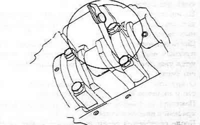
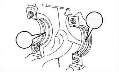
Clean the bearing holes and place the bearing shells with lubrication channels in the holes so that the projections in the shells fit into the recesses of the holes (arrows). The shells must be well lubricated.
Place both adjusting washers installed in the block on the middle bearing. Carefully lower the crankshaft into the bearing shells. If the connecting rods are still in the cylinder block, you need to bring the connecting rod bearings to the crankpins. Place the lower bearing shells in the corresponding bearing caps (protrusions into recesses) and lubricate the surfaces well. Install the other two adjusting washers. They should also be well lubricated. The lubrication channels should match.
Place the covers on the cylinder block and hammer in with a rubber or plastic hammer. Tighten the cover bolts, starting from the middle and moving towards the edges, in several passes with a tightening torque of 65 Nm. After tightening the covers, turn the crankshaft several times to determine if there is any jamming. Check the axial clearance again, as already described when removing the crankshaft.
Install pistons and connecting rods.
Install both seals.
Install the crankshaft drive gear with key.
Install the drive belt as described in the next section and install the cover.
On vehicles with a manual transmission, install the flywheel. The bolts must be replaced each time. The bolts must be tightened according to the type of flywheel as follows:
- If a conventional flywheel is installed, the bolts should be tightened to a torque of 6 Nm and from this position tightened another quarter of a turn (90°).
- If a dual flywheel is installed, tighten the bolts to 4Nm and from this position tighten another half turn (180°).
- In both cases, the crankshaft should be held by inserting a wooden block between the crank arm and the engine crankcase wall, or by placing a metal strip on the other side.
After installing the flywheel, you need to install the clutch and tighten the bolts.
On cars with automatic transmission, a drive plate must be installed. One washer is located between the drive plate and the crankshaft, and the second washer is between the bolt and the plate. The bolts are tightened in the same way as with a conventional flywheel. Before installing the drive plate, you must read the relevant section, since a certain distance must be established between the drive plate and the cylinder block.
Install the oil pump.
Glue the new oil pan gasket with grease and install the oil pan. Tighten the hex bolts to 20 Nm.
All other operations are performed in the reverse order of removal.