
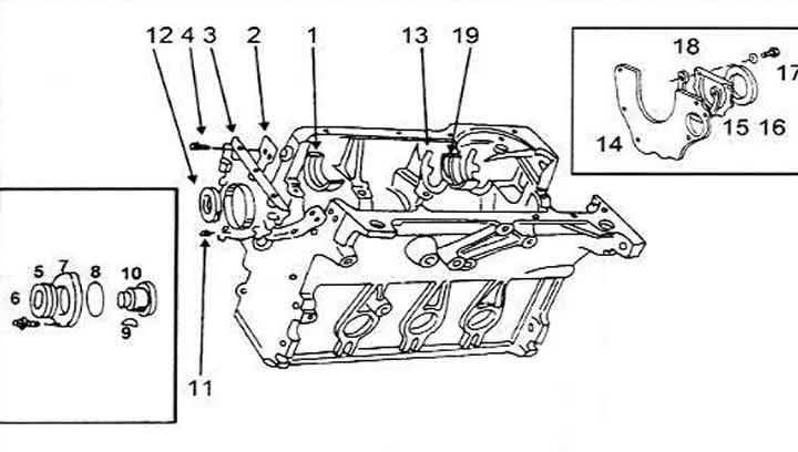
Cylinder block and parts bolted to it
1 Bearing insert in the block (with lubrication groove)
2 Gasket
3 Front sealing flange
4 Bolt
5 Seal
6 Bolt, 25 Nm
7 Seal flange
8 Sealing ring
9 Key
10 Intermediate shaft
11 Bolt, 10 Nm
12 Crankshaft oil seal
13 Adjusting washer in the block
14 Engine Intermediate Plate
15 Rear oil seal flange
16 Rear oil seal
17 Bolt, 10 Nm
18 Gasket
19 Bearing support No.3
The cylinder bores need to be checked carefully. By running the tip of your finger along the top and bottom of the bore, you can determine the wear, which appears as a "step" if the piston does not move along the entire bore, and therefore wear occurs. This is an indication that the bores need to be reamed. Pistons of repair sizes are available.
To measure piston clearances, you need to measure the piston diameters and record the diameters of all pistons along with the cylinder numbers. You will need to use a micrometer here. If you cannot fully rely on your skills, have a workshop take the measurement.
To determine the clearances, it is now necessary to measure the diameters of the cylinder bores as follows:
Using a pointer gauge, measure the diameters of the holes at a distance of 10 mm from the upper edge of the hole and then at a distance of 10 mm from the lower edge of the hole. You need some experience to work with a pointer gauge. The pointer gauge is inserted into the hole. If you shake the gauge from left to right and back, the needle of the gauge will also move from left to right and back again. The average value of the needle movement is important, as it gives the exact diameter value. You need to measure in the longitudinal and transverse directions.
The numbers 1, 2 and 3 indicate the locations of measurements inside the bore. The letters (A) and (B) indicate the direction in which measurements should be taken. The graph shows a normal wear curve, labelled "a", and a premature wear curve, labelled (1).
Take another measurement in the middle.
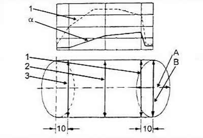
Perform the above measurements in the longitudinal direction of the cylinder block and then again at the same depths in the transverse direction of the block. All six values obtained should be recorded. The difference between the measured values at the top and bottom gives the narrowing value. The difference between the measured values in the longitudinal and transverse directions gives the value of the difference from the circumference. In no place should the diameter differ from the nominal value by more than 0.08 mm.
For each engine type there are several piston oversize sizes, and the cylinder block can be bored to the next size.
The cylinder block surface should be checked for warpage. The block should be measured in the longitudinal, transverse and diagonal directions. It should not be possible to insert a feeler gauge with a thickness of more than 0.10 mm. Before taking measurements, make sure that the cylinder block surfaces are thoroughly cleaned and that no foreign bodies have gotten between the ruler and the cylinder block surface.
[The original version is on the portal: audimanual.ru]