
Table of contents: Compression pressure too low ↓ Troubleshooting ↓ System leak test ↓ Cranking the engine crankshaft ↓ Removal the cylinder head cover ↓ Removal the engine protective cover ↓
Compression pressure too low
Consistently low compression pressure is not necessarily a warning sign; the reason for this may also be the measurement tolerances of various control devices. However, you should think about it if differences of more than 2-3 bar are measured between individual cylinder readings. This may mean:
Wear of pistons and piston rings.
Coking of piston rings due to deposit formation.
Elliptical shape in cylinders as a result of piston seizure.
Deposits on valve stems or seats due to combustion residue or oil.
Burnt valves: In most cases, loose valves are the cause of insufficient compression pressure and thus reduced engine power.
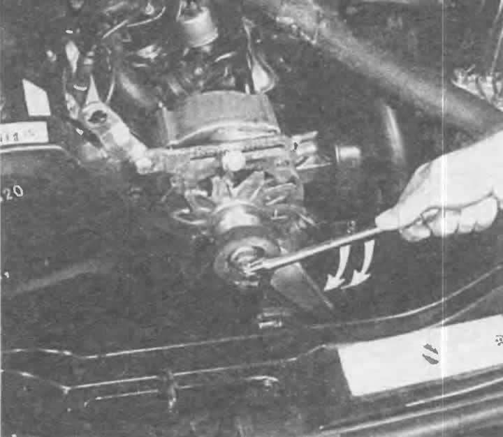
To turn the crankshaft of a 4-cylinder engine manually, place a 22 mm wrench on the alternator pulley nut. If the belt slips, press on it.
Troubleshooting
To more accurately determine the malfunction with low compression, you should use the following trick: drip a little oil from an oil can into the spark plug hole and measure the pressure again.
If the readings are still low, it's all about the valves.
If you get higher readings, the piston rings are the cause, or perhaps the cylinders as well. The added oil created a better seal between the pistons and the cylinder walls for a short time, so that the compressed gas could hardly escape.
System leak test
More accurate results can be obtained by checking the system for leaks, which some workshops can do by directing compressed air into the combustion chamber through the spark plug holes.
If the combustion chamber being tested loses pressure, this can be seen on the scale of the control device. A relatively large leak can be identified by listening:
- Trumpeting sounds near the exhaust pipe indicate a leaky exhaust valve.
- If air comes out of the air filter housing, the intake valve is faulty.
- If the cylinder head gasket is faulty or the cylinder head is cracked, compressed air will leak out of the adjacent spark plug hole or from the open coolant expansion tank.
- Worn cylinder walls, cylinder bores or piston rings allow air to enter the crankcase, where it exits through open oil filler pipes or the dipstick guide tube.
Cranking the engine crankshaft
To carry out some work, it is necessary to either bring the crankshaft to a certain position or turn it.
To do this, in a car with a manual transmission on a level surface, you need to engage fifth gear and roll the car forward or backward a little. Or:
On a 4-cylinder engine, place a 22 mm offset open-end wrench on the central nut of the alternator pulley and turn the engine over the V-belt. If the belt slips, press it between the pulleys with your free hand to tighten it.
Unscrew the V-belt cover in a 5-cylinder engine.
Measuring the compression ratio pressure. The compression ratio pressure measuring device shown here (compression meter) with a measuring card is available in the workshop. For home use, simpler control devices with a pointer are suitable, in addition, they are cheaper.
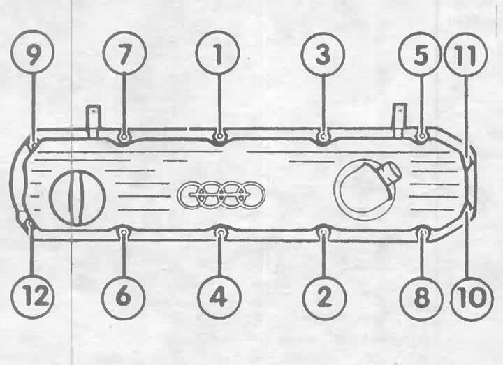
The cylinder head cover nuts of a 5-cylinder engine must be tightened in the following sequence, first with a tightening torque of 5 Nm, then 10 Nm and finally 12 Nm.
Place a 32mm open-end wrench on the servo pump adapter and turn the engine over the V-belt.
On a 6-cylinder engine, place a 12-point 24mm socket wrench on the crankshaft pulley center bolt and turn the crankshaft with a ratchet or pry bar.
Never turn the engine by the timing belt pinion mounting bolt on the camshaft with the timing belt cover removed! The timing belt may jump, resulting in engine damage.
Setting cylinder 1 to the top dead center (TDC) position of the ignition timing
In a four-stroke engine, the piston reaches the top dead center (TDC) twice: the first time when the injected combustible mixture is ignited, and the second time after the exhaust gases are ejected, with the fuel/air mixture finally being sucked in again. Usually, the TDC of the ignition moment of the first cylinder is required for various adjustments.
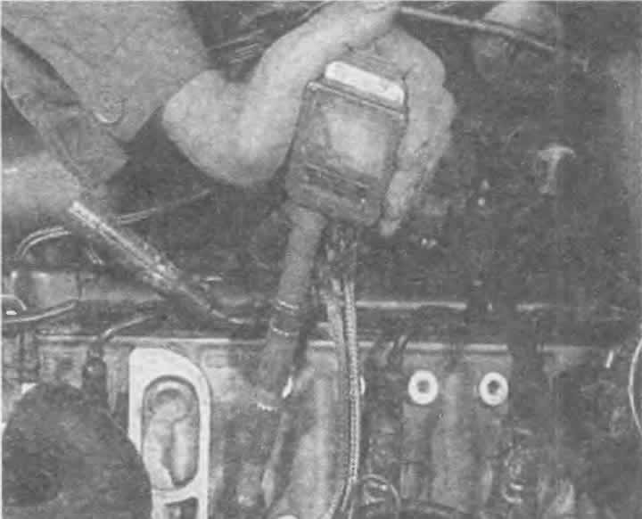
4-cylinder and 5-cylinder engines: remove the cover separating the breaker from the distributor, the distributor rotor and the protective cover. Put the distributor rotor back on and turn the engine until the rotor contact is above the small mark on the edge of the distributor. This has found TDC.
To get this as accurate as possible, you will probably need to turn the crankshaft a little one way or the other until the "O" mark on the flywheel appears at the edge of the inspection hole in the transmission.
6-cylinder engine: remove the timing belt cover on the right and left (described later in this chapter).
Turn the crankshaft until both holes in the locking plates on both camshaft drive gears are aligned inward opposite each other.
Turn the crankshaft slightly in one direction or the other until the "O" mark appears on the flywheel at the edge of the inspection hole in the gearbox cover.
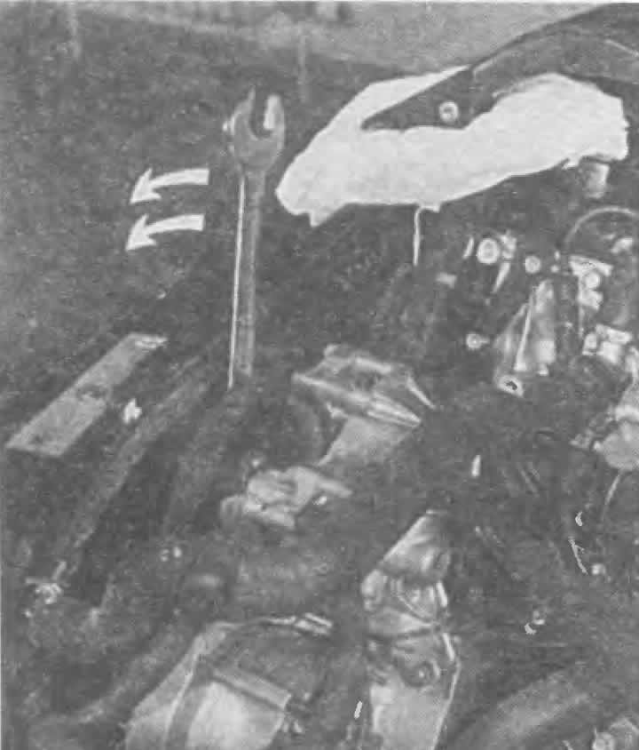
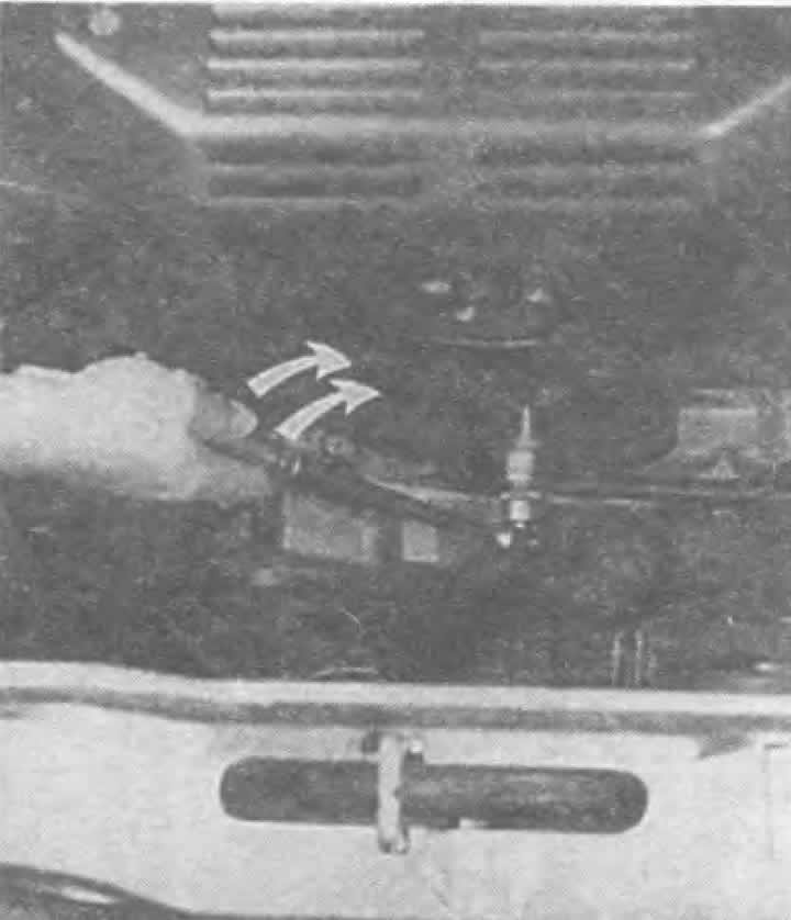
In a 5-cylinder engine, the crankshaft can be turned at a special adapter in front of the power steering pump. To do this, place an open-end wrench on the hex adapter, as shown in the figure. First remove the V-belt cover (one bolt).
The crankshaft of a 6-cylinder engine is turned by the central bolt of the crankshaft pulley. The tool used is a 12-sided replaceable socket head 24 mm with a ratchet or lever.
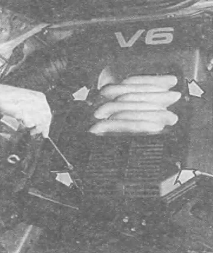
The 6-cylinder engine cover shown here was not immediately available on production engines. The arrows indicate four quick-release fasteners that must be turned 90° to the left to remove the cover.
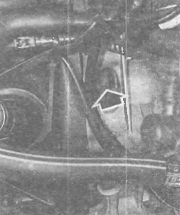
TDC is found if the "O" mark appears on the flywheel under the edge of the gearbox housing (arrow).
Removal the cylinder head cover
The latest 6-cylinder engines are equipped with a protective cover, which, in addition to looking good, also serves as a noise absorber.
Removal:
Turn the four quick-release fasteners 90° to the left with a large screwdriver.
Remove the protective cover.
Removal the engine protective cover
4-cylinder engine: Remove the crankcase ventilation hose. If necessary, disconnect the wiring harness.
Loosen the throttle cable and pull it out of the support.
Loosen the fastening nuts.
Remove the stiffening pads.
Lift the lid.
If necessary, remove the oil deflector.
5-cylinder engine: Remove the brake booster hose from the intake manifold.
Remove the upper part of the intake manifold and the injection nozzles (chapter "KE-III-Jetronic and KE-Motronic injection system").
Remove the idle speed control valve.
Unscrew the fastening nuts and remove the stiffening pads.
Remove the cover.
6-cylinder engine: remove engine protection.
Loosen the locking bolts.
Lift the lid.
If necessary, remove the oil deflector.
When installing, if possible, install a new gasket.
4- and 5-cylinder engines: don't forget about the stiffening sheet under the mounting nuts.
6-cylinder engine: Lightly lubricate the cylinder head cover gasket on the inside and outside with silicone anti-friction agent D 007 000 04.
Apply a little "Silimate" AMV 174 004 01 from the Audi Parts Warehouse to all four surfaces between the cylinder head gasket and the camshaft bearing cap. Make sure that the oil hole at the bottom of the camshaft bearing cap does not become clogged.
All engine types: tighten the nuts or bolts crosswise to 10 Nm, starting from the middle of the cover. In a 5-cylinder engine, additionally pay attention to the tightening sequence and torques (illustration top left).
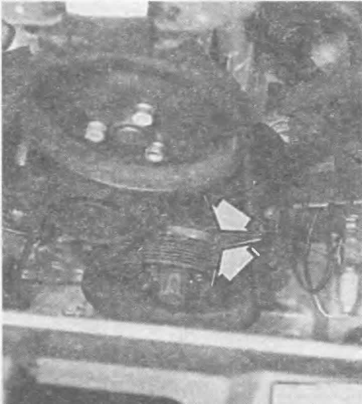
Another TDC mark on 6-cylinder engines is located on the pulley or lower protective cover of the toothed belt (arrows).
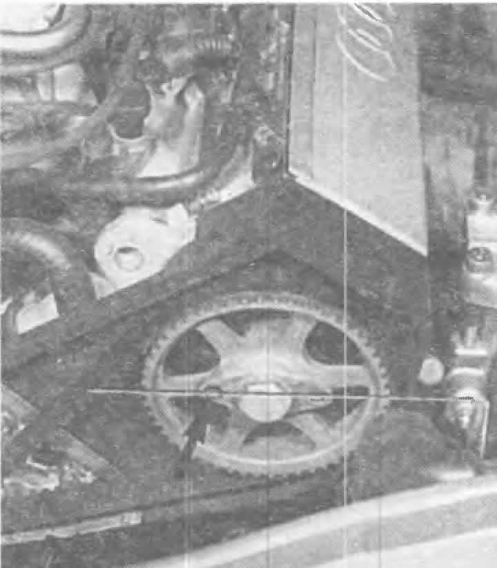
At TDC of the ignition moment of the first cylinder, the large holes of the mounting plates on both drive gears of the camshaft are directed towards the middle of the engine (arrow). The flange of the camshaft gear should be located horizontally (so that an imaginary horizontal line is formed).
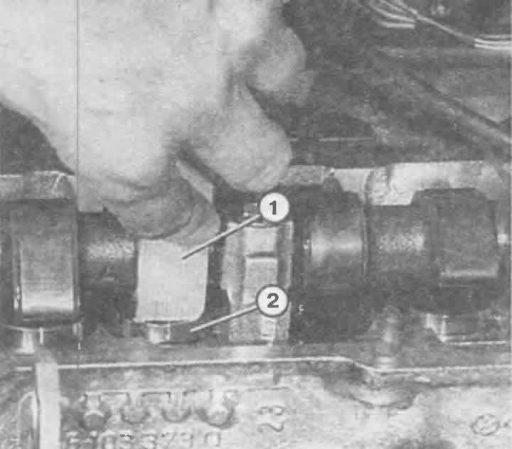
To check the hydraulic tappets, press a plastic or wooden wedge (1) onto the unloaded hydraulic tappet (2). Metal tools that can easily scratch the surface of the hydraulic tappet must not be used.