
Table of contents: Pistons, connecting rods, cylinders ↓ Crankshaft ↓ Cylinder head and camshaft ↓ Hydraulic tappets ↓ Operation of hydraulic tappets ↓ Toothed belt ↓ Cylinder head gasket ↓
For those interested in how an engine works, below is a brief description of the most important parts before we move on to repairs and maintenance.
Pistons, connecting rods, cylinders
In the upper third of each piston, three piston rings are elastically inserted into the corresponding grooves. They, cushioning, press on the cylinder wall. Both upper piston rings do not allow gases from the combustion chamber to pass down into the crankcase, while the lower oil scraper piston ring prevents excessive lubricant from the crankcase from entering the combustion chamber. The cylinders in which the pistons move up and down are located in the cast-iron cylinder block of the engine. The inner cylinder walls are ground with a cross-grinding. The cylinder walls must not be completely smooth, because otherwise the oil necessary for lubrication will not be able to stick to them. When repairing the engine, the working surfaces of the cylinders can be ground up to two times.
Crankshaft
The job of the crankshaft is to convert the linear motion of the pistons moving up and down in the cylinder into rotational motion.
The connecting rods leading to the pistons act on the crankshaft, they are located on the crankpins of the crankshaft. To prevent excessive vibration, counterweights are placed opposite the crankpins.
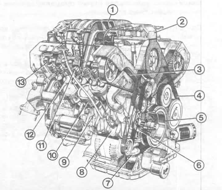
6-cylinder engine in section:
1 - intake gas line;
2 - ignition coil pack;
3 - toothed belt;
4 - poly V-belt;
5 - pulley with damper on the crankshaft;
6 - oil pump;
7 - oil pump inlet pipe;
8 — crankshaft;
9 — connecting rod;
10 — piston;
11 - hydraulic tappets;
12 — valve;
13 — camshaft.
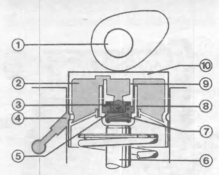
Valve actuation by hydraulic tappet: oil under increased pressure is marked in red. Light red indicates the amount of oil not needed to actuate the valves. The numbers mean:
1 - camshaft eccentric;
2 - oil tank;
3 - check valve;
4 - oil inflow;
5 - high pressure chamber;
6 - valve stem;
7 — compression spring;
8 — cylinder;
9 — piston;
10 - hydraulic pusher.
To prevent the crankshaft from bending during operation, it is located on five bearings in a 4-cylinder engine, and on six bearings in a 5-cylinder engine - main journals. Each "knee" located on the connecting rod is thus supported by a bearing on the right and left. It is different in a 6-cylinder engine: for reasons of space saving, two connecting rods are always located between two main bearings. Thus, such an engine has a total of 4 main main bearings.
At the rear of the crankshaft, in the direction of travel, there is a disk with a toothed ring for the starter pinion. This is the flywheel on which the clutch is mounted and thus the connection with the gearbox is carried out, or the driven disk to which the torque converter of the automatic transmission is attached. At the front end of the crankshaft, there is a gear for the toothed belt drive.
Cylinder head and camshaft
The cylinder head is, in a sense, the upper boundary of the combustion chambers. At the very top of the cylinder head is the camshaft. With its eccentrics, it forces the valves to open and close at certain piston positions. In this way, it determines the valve timing. The camshaft is driven by the crankshaft via a toothed belt.
But the valve drive does not occur directly through the camshaft. The intermediate instance is the so-called plate tappets. Each such plate tappet is placed on the valve stem.
Hydraulic tappets
The hydraulic valve clearance adjustment is built into the already mentioned plate hydraulic tappets. This device means that the previously necessary valve clearance control can now be omitted: the valve drive operates with the clearances set by the manufacturer and ensures flawless operation throughout the entire service life of the engine.
Note: An engine with hydraulic tappets may make loud knocking noises when first started after a long period of inactivity. No need to worry: after a short time, this noise disappears and the valve drive operates silently again. However, if one of the hydraulic tappets continues to knock for a long time even when the engine is warm, it should be checked.
Operation of hydraulic tappets
When the valve is closed, oil from the engine lubrication system enters the plate tappet through the annular groove. After passing the check valve in the tappet, the lubricant enters the still empty high-pressure chamber and completely fills it. In addition, the spring presses the plate tappet against the camshaft.
If the camshaft now turns and its eccentric presses on the plate tappet, the pressure in the chamber increases. The check valve closes the inlet, so that the oil can no longer escape. Since the oil is incompressible, a rigid connection is thus established between the plate tappet and the cylinder. That is, the valve can be pushed down by the force of the cam.
After the valve closes, a small gap is created due to oil leakage, which is, however, immediately balanced by the compression spring, which pushes the plate tappet upwards. Oil rushes into the increased volume of the high-pressure chamber again with the check valve open. The hydraulic tappet is thus ready for the next valve drive.
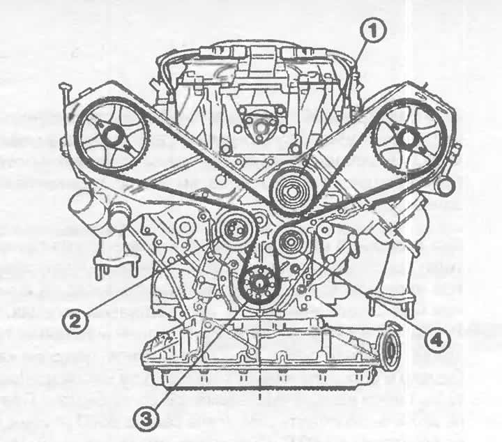
The figure shows the passage of the toothed belt in a 6-cylinder engine. The numbers indicate:
1 - coolant pump pulley;
2 - tension roller;
3 - toothed pulley of the crankshaft belt;
4 — guide roller.
Toothed belt
The toothed belt, driven by the crankshaft, is a virtually silent element of the camshaft drive. The toothed rubber belt, reinforced with steel wire, operates without wear, and the rubber compound of the toothed belt provides dry lubrication of the pulleys. In addition to the camshaft, the toothed belt drives the coolant pump on models with 5- and 6 - cylinder engines. On models with 4 - cylinder engines, the belt also drives the intermediate shaft, which in turn drives the oil pump and distributor.
Cylinder head gasket
The gasket between the cylinder block and the cylinder head provides isolation between the combustion chambers and the coolant and oil passages. At the same time, it must withstand extreme temperature and pressure fluctuations.