
Table of contents: Removal ↓ Installation ↓
Front door
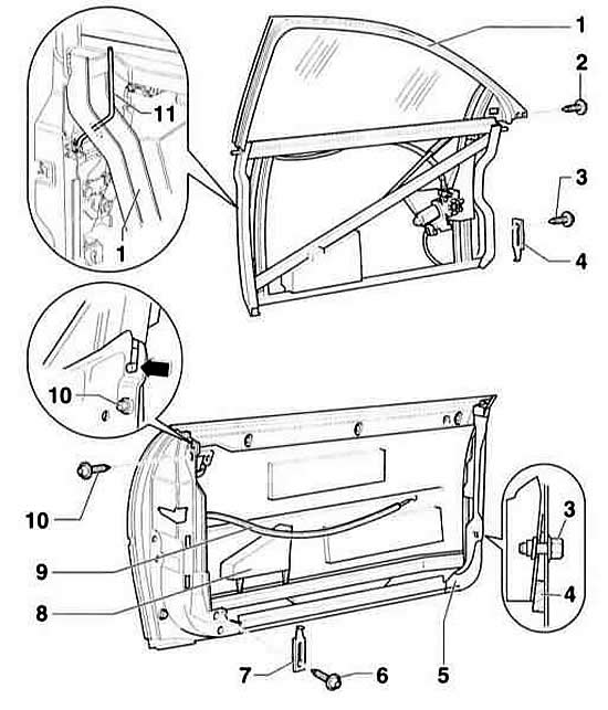
- 1 - holder
- 2 - bolt, 30 Nm. M8 x 26
- 3 - bolt, 30 Nm. M8 x 32
- 4 - Adjusting wedge. Must always be installed
- 5 - door. The door can also be removed without removing the holder of the adjustment elements
- 6 - bolt, 30 Nm
- 7 - Adjusting wedge. Must always be installed
- 8 - side stop shield
- 9 - drive cable
- 10 - bolt, 30 Nm. M8 x 26
- 11 - locking rod
Removal
Warning: The door can also be removed without removing the adjuster holder. In this case, it is not necessary to remove the holder.
1. Remove the door trim, refer to subsection Removal and installation door trim.
2. Remove the A-pillar trim (bottom), refer to subsection Removal and installation the A-pillar trim.
3. Disconnect the electrical wires and the vacuum hose of the single lock from the holder –1–.
4. Disconnect the cable –9– from the holder.
5. Remove the bolts (2, 3, 6 and 10). In this case, remove the adjusting wedges –4– and –7–.
6. Pull the adjusting element holder upwards.
7. Remove the cover between the door and the A-pillar.
8. Remove the bushing from the A-pillar.
9. Remove the electrical wires and the single lock vacuum hose from the A-pillar.
10. Disconnect the electrical wires and vacuum hose at the A-pillar. Disconnect the single lock hose plug, refer to subsection Single Lock - General Information and Vacuum Hoses.
11. Be careful that the connector does not slip into the A-pillar. Secure it with a clip.
12. Ask an assistant to support the door.
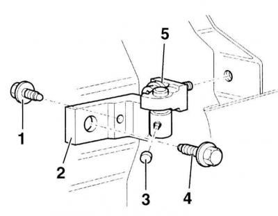
- 1 - bolt, installed from the inside, 30 Nm
- 2 - upper door hinge
- 3 - cover, 23 Nm
- 4 - bolt, 30 Nm
- 5 - Torx screw, 30 Nm
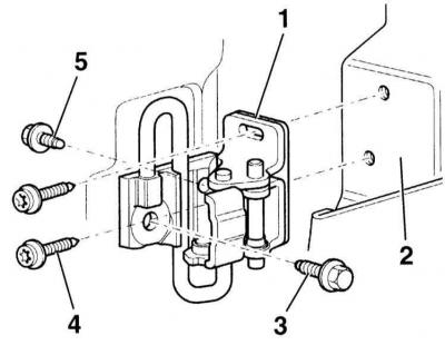
- 1 - lower loop
- 2 - front door
- 3 - bolt, 30 Nm
- 4 - Torx screw, 30 Nm
- 5 - bolt, 30 Nm
13. Unscrew the Torx T45 screws from the door side near the hinges at the top and bottom.
14. Remove the door with the help of an assistant.
Installation
1. Install the door into the hinges with the help of an assistant and secure with Torx T45 screws. Tightening torque 30 Nm.
2. Insert the electrical wires and vacuum hose of the single lock into the A-pillar connector.
3. Insert the electrical wires and vacuum hose into the A-pillar.
4. Secure the bushings to the A-pillar.
5. Insert the casing between the door and the A-pillar.
6. Insert the holder into the door from above.
7. Secure the holder with bolts. Do not forget about the adjusting wedges of bolts –3– and –6–, refer to the illustration. Tightening sequence: (2, 10, 6, 3). Tightening torque 30 Nm. Adjustment of wedges is discussed in the subsection Door adjustment.
8. Connect the cable –9– to the holder.
9. Connect the electrical wires and the vacuum hose of the single lock, lay them down and secure them, refer to the subsection Single Lock - General Information and Vacuum Hoses.
10. Adjust the door.
11. Install the A-pillar trim, refer to subsection Removal and installation the A-pillar trim.
12. Install the door trim, refer to the subsection Removal and installation door trim.
[The original material is located on the website audimanual.ru]