
Table of contents: Outside door handle and door lock ↓ Removal and installation the lock… ↓ Remove the lock cylinder cap ↓ External door handle ↓ Removal and installation the… ↓ Removal and installation the… ↓ Removal and installation the front… ↓ Lock bracket, door lock, door… ↓ Removal and installation the lock… ↓ Removal and installation the door… ↓ Removal and installation the door… ↓ Removal and installation the door… ↓ Removal and installation the support… ↓ Removal and installation the door… ↓
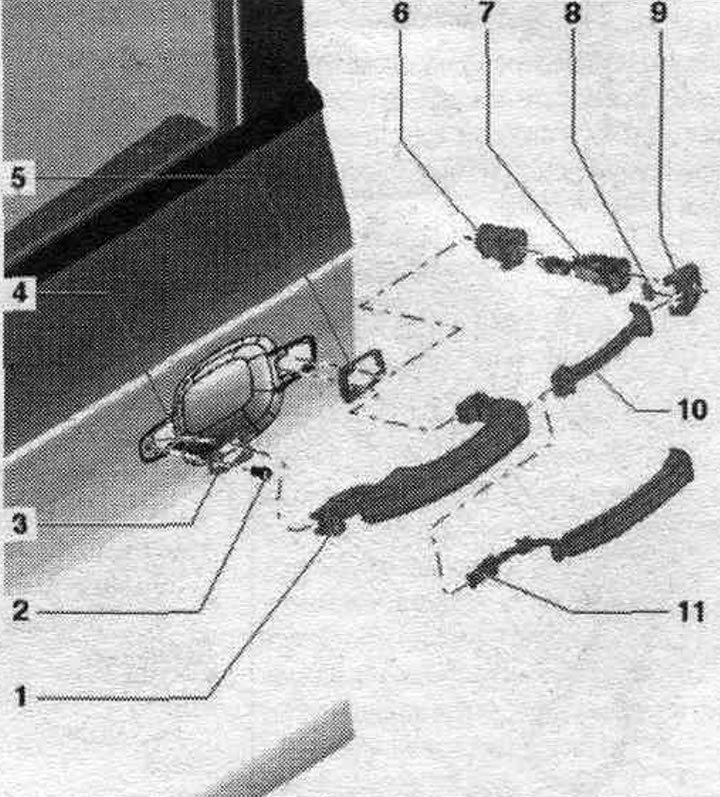
Outside door handle and door lock
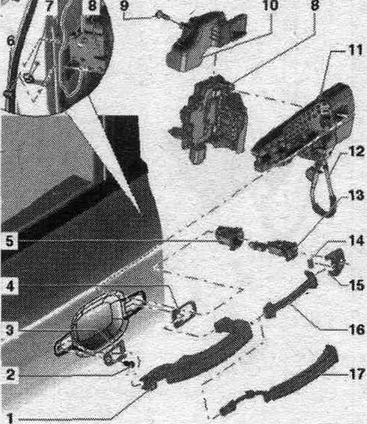
1. Outside door handle.
2. Bolt: 2.5 Nm.
3. Front lining.
4. Bottom lining.
5. Case: instead of the lock cylinder; for the door per. passage.; removal and installation as for the lock cylinder.
6. Bolt.
7. Cover: Unlock before removing the door handle.
8. Door lock.
9. Bolt: 3.5 Nm.
10. Overlay: with door lock trim.
11. Pen body.
12. Door lock control rod.
13. Lock cylinder: for door driver only.
14. Magnet: only for vehicles with "Keyless entry system".
15. Cover: driver's side: for cylinder cylinder, front side. passage: closed execution.
16. Outside door handle strip: for vehicles without "Keyless entry system".
17. Door handle touch sensor: for vehicles with "Keyless entry system".
Removal and installation the lock cylinder
1. Lid.
2. Magnet: only for vehicles with "Keyless entry system".
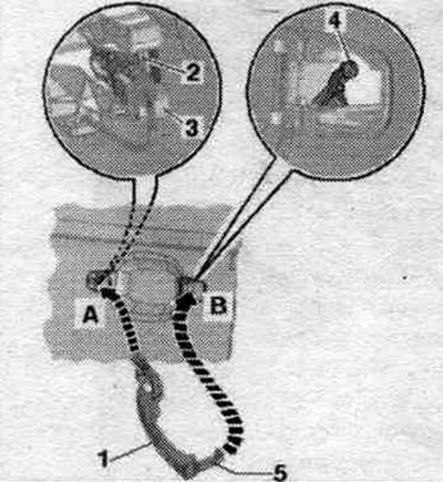
3. Lock cylinder: unlock the trim on the front side of the door: completely unscrew the clamp bolt with a screwdriver; press the fastening bracket with a screwdriver and remove the lock cylinder with the cap on the side.
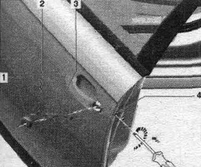
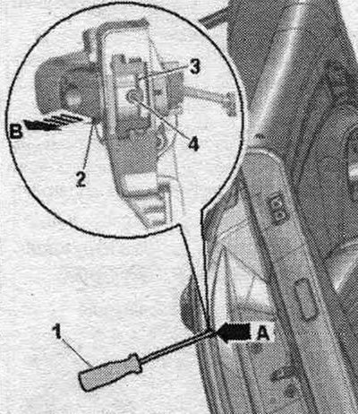
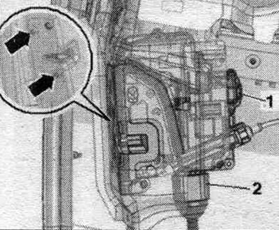
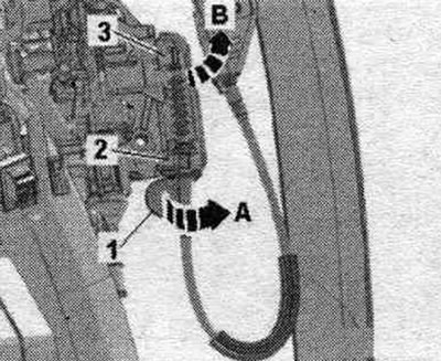
Move the door seal to the side and remove the trim above the hole marked "arrow A." Fully unscrew the clamp bolt "4" using screwdriver "1." Press the locking latch "3" of the lock cylinder inward. Remove lock cylinder "2" from the support bracket "arrow B." If the lock cylinder cannot be removed, insert the ignition key into the lock cylinder and remove it by gently turning the key.
Installation
Installation in reverse order. Insert the lock cylinder into the support bracket, and then make sure that the door lock opens and closes.
Remove the lock cylinder cap
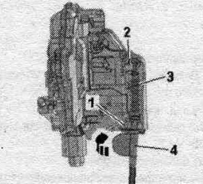
Remove the lock cylinder. Loosen the fastening clamps "arrows" and remove the cap "1" from the lock cylinder "2", if necessary, use a small screwdriver.
Installation
Installation in reverse order. Place the cap on the lock cylinder until it clicks into place.
External door handle
1. Outside door handle.
2. Bolt: 2.5 Nm.
3. Front lining.
4. Door.
5. Bottom lining.
6. Case: instead of the lock cylinder; for the door per. passage.; removal and installation is carried out in the same way as for the lock cylinder.
7. The door lock cylinder is driven.
8. Magnet: only for vehicles with "Keyless entry system".
9. Cover: secure to the lock cylinder.
10. Outside door handle strip: for vehicles without "Keyless entry system".
11. Door handle touch sensor: for vehicles with "Keyless entry system".
Removal and installation the exterior door handle
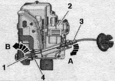
Move the door seal aside and remove the trim above the opening marked "arrow A." Fully unscrew the clamp bolt "4" using screwdriver "1." Pull the outer door handle and hold it in the "Open" position. Press the lock cylinder mounting brackets "3" inward; the outer door handle will lock in the "Open" position. Remove the lock cylinder "2" from the support bracket marked "arrow B." If the lock cylinder cannot be removed, insert the ignition key into the lock cylinder and remove it by gently turning the key. Pull the outer door handle "1" in the direction of the arrow, this will remove the outer door handle from the drive lever in the support bracket.
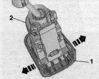
Tilt the outer door handle "1" outward "arrow" and remove it from the mount on the support bracket. On vehicles with "Keyless Entry System", disconnect plug "2" from the outside door handle.
Installation
Installation in reverse order. Replace damaged or brittle outer door handle washers "1" and "2".
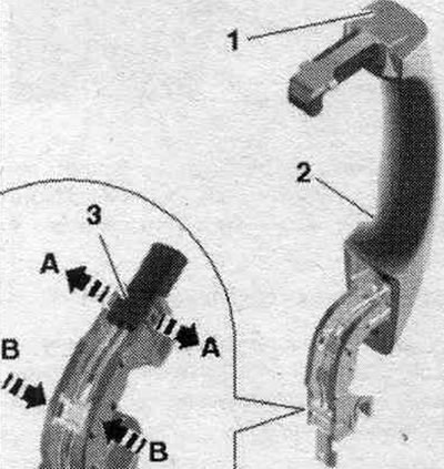
Insert the outer door handle "1" "arrow A", in doing so the outer door handle must engage in the retainer "2" on the support bracket "3". Tilt the outer door handle "1" "in the direction of arrow B" and insert the lever "5" in front of the drive lever "4" in the support bracket. Press the retaining clip of the outer door handle lock cylinder. Install the lock cylinder.
Removal and installation the exterior door handle
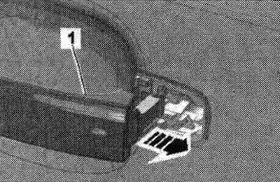
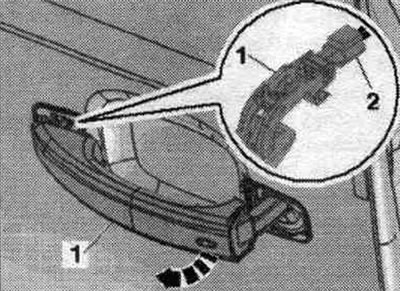
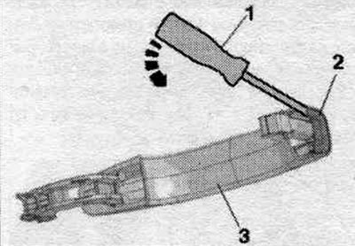
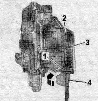
On cars without a "Keyless Entry System", a cover is installed instead of the door handle touch sensor. Remove the outside door handle. Pry up the cover plate "1" of the door handle using screwdriver "2" in the place shown in the figure "Arrow". Remove the cover from the outer door handle "3".
Installation
Installation in reverse order. Insert the outer door handle cover until it clicks into place. Install an exterior door handle. Install the lock cylinder.
Removal and installation the front door outer handle sensor "G605"/"G606"
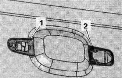
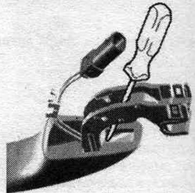
Remove door handle "2" with sensor "1".
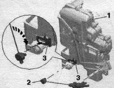
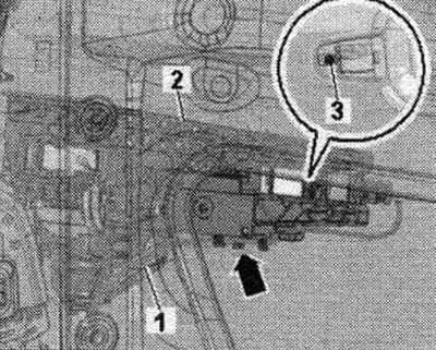
Carefully unfasten the clamps at the arrows - A and B- using a small screwdriver and push connector "3" with the wiring to the side. Place a screwdriver in front of the sensor as shown in the picture Press the sensor forward with a slight twist of a screwdriver from the door handle. Remove the sensor from the door handle.
Lock bracket, door lock, door release handle drive cable
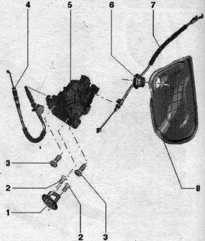
1. A bracket with a finger under the latch of the lock.
2. Bolt: 25 Nm.
3. Bolt: 19 Nm.
4. Door lock drive cable. To prevent the drive cable from bending or breaking too much during removal and installation, the door lock must be removed and installed together with the support clamp. The drive cable outside the door must be removed and installed on the control lever on the door lock.
5. Door lock.
6. Nozzle: not a spare part.
7. Door handle drive cable.
8. Lining the inner door panel.
Removal and installation the lock bracket
Unscrew bolts "2" and lock bracket "1".
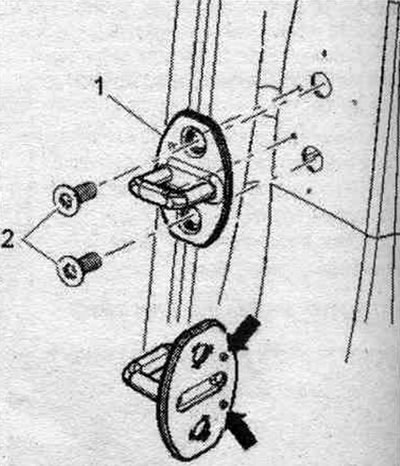
Installation in reverse order. The lock bracket lining with the "arrow" contacts must be located exactly in the hole. After moving the lock bracket, the contacts should be cut evenly. When installing a new part, the cut contacts of the lock bracket must be removed from the vehicle.
Removal and installation the door lock trim
Remove the lock cylinder. Remove the door trim. Remove the inner door panel trim. Unscrew bolt "4". Squeeze lock "3" and slide trim "2" back from door lock "1".
Installation
When installed, the latch "3" should snap into the door lock. Tighten bolt "4" to the specified torque. puffs.
Removal and installation the door lock
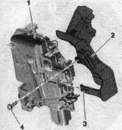
Remove the lock cylinder. Remove the door trim. Remove the inner door panel trim. Remove the door lock trim. Rotate the drive cable on lever "1" 90° in the direction of arrow A and remove it from the cable support "2". Rotate the drive cable on the door lock drive lever "3" in the direction of arrow B. The drive cable should be aligned with the hole in the drive lever. Remove the drive cable from the drive lever.
Unscrew the "arrow" bolts. Remove door lock "1" and disconnect the plug connector "2".
Installation
Installation in reverse order. Insert the drive cable "3" from the drive lever "2" of the door lock. Insert the drive cable into the support "1" and turn the lever "4" 90° "arrow". The lever protrusion must engage in the cable support.
Install the door lock trim. Install the interior door panel trim. Install door trim. Install the lock cylinder.
Removal and installation the door handle drive cable
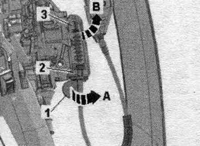
Remove the lock cylinder. Remove the door trim. Remove the inner door panel trim. Remove the door lock trim. Unscrew the "arrow" bolts. Press the door lock "1" to the side and. if necessary, disconnect the plug connector "2". Disconnect the drive cable "3" on the door lock cable support "2" "arrow A". Turn the nipple "1" 90° "in the direction of arrow B" and remove it from the door handle release lever "4".
Installation
Installation in reverse order. Insert the nipple "2" into the door handle release lever "3" "lower arrow". Turn the nipple 90° — upper arrow — and press the drive cable into the door lock cable support "1" until it audibly engages. Install the door lock trim. Install the interior door panel trim. Install door trim. Install the lock cylinder.
Removal and installation the support bracket
Remove the door trim. Remove the inner door panel trim. Rotate the drive cable on lever "1" 90° in the direction of arrow A and remove it from cable support "2". Rotate the drive cable on door lock drive lever "3" in the direction of arrow B. The drive cable should be aligned with the hole in the drive lever.
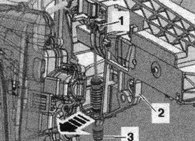
Remove the drive cable from the drive lever. Remove the outside door handle. Remove the door lock trim. Disconnect (if available) wire from the "arrow" support bracket. Release the "1" electrical wire tie using the "80-200" lever. Use a soap solution to facilitate removal. Unscrew bolt "3" and remove support bracket "2".
Installation
Installation in reverse order. Insert the drive cable "3" from the drive lever "2" of the door lock. Insert the drive cable into the support "1" and turn the lever "4" 90° "arrow". The lever protrusion must engage in the cable support.
Install the door lock trim. Install the interior door panel trim. Install door trim. Install an exterior door handle.
Removal and installation the door lock drive cable
Remove the door trim. Remove the inner door panel trim. Rotate the drive cable on lever "1" by 90° in the direction of arrow A and remove the cable iso-supports "2". Rotate the drive cable on the door lock drive lever "3" in the direction of arrow B. The drive cable should be aligned with the hole in the drive lever. Remove the drive cable "1" from the drive lever; to do this, press the support "3" out of the retainer on the support bracket "2" "arrow". Remove the drive shaft.
Installation
Installation in reverse order. Insert the drive cable "3" from the drive lever "2" of the door lock. Insert the drive cable into the support "1" and turn the lever "4" 90° "arrow". The lever protrusion must engage in the cable support. Install the interior door panel trim. Install door trim.