
Table of contents: Removal ↓ Installation ↓
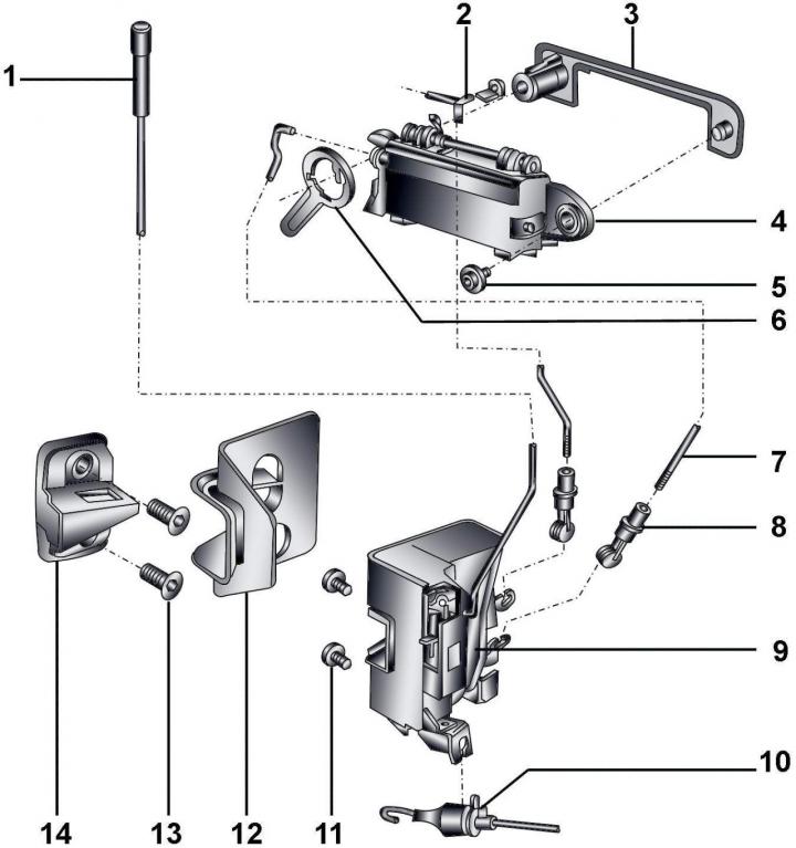
Fig. 16–31. Front door lock: 1 – lock button; 2 – lock cylinder rod; 3 – external element of the lock; 4– door handle; 5 – bolt, 5 Nm; 6 – rotary clamp; 7 – lock rod; 8 – hinge clamp; 9 – door lock; 10 – cable of the inner door opening handle; 11 – bolt, 8 Nm; 12 – lock support plate; 13 – screw, 16 Nm; 14 – impact plate
The front door lock is shown in Fig. 16–31.
Removal
Remove the door trim.
Remove the bracket from the door.
Release the connector and remove the lock release button.
Remove the split bushings and disconnect the rods from the lock cylinder and the outer door opening handle.
Rotate the lower link joints 90° and remove them from the door lock levers.
Unscrew the two door lock mounting bolts.
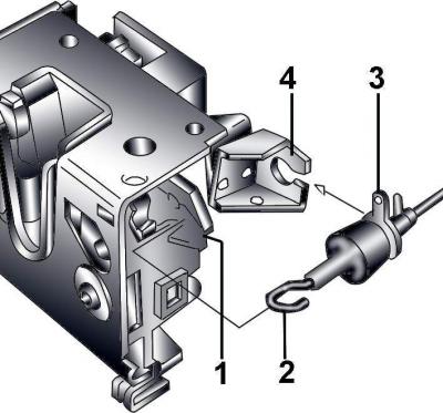
Fig. 16–32. Fastening the tip (1) of the inner door opening handle rod to the lock control lever (2) and the guide rod (3) to the lock bracket (4)
Disconnect the ring end 1 (Fig. 16–32) of the inner door opening handle rod from the lock control lever 2 and remove the rod guide 3 from the lock bracket 4, after turning it 90°.
Remove the lock from the door.
If necessary, unscrew the two bolts and remove the door lock strike plate.
Installation
Installation is carried out in the reverse order of removal, taking into account the following.
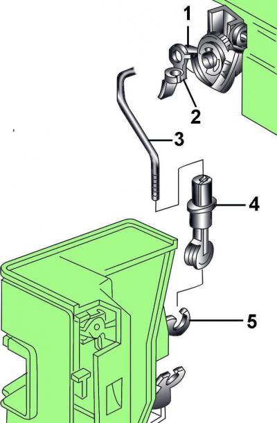
Fig. 16–33. Fastening the door lock lock rod: 1 – lock cylinder lever; 2 – split bushing; 3 – traction; 4 – traction joint; 5 – lock lever
Install rod 3 (Fig. 16–33) into lever 1 of the lock cylinder and secure the rod with split sleeve 2.
Screw joint 4 of rod 3 onto rod.
Install the lower rod joints onto the lock levers and rotate them 90°.
Secure the lock cylinder with a retaining ring.
Place the lock back in place and secure it with bolts.