
Withdrawal
Remove the door trim.
Remove the bracket from the door.
Disconnect the rods from the lock cylinder and door handle.
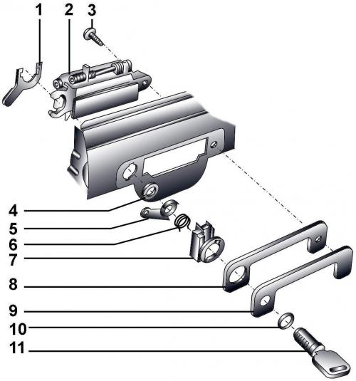
Pic. 16–34. Front door handle: 1 - swivel clamp; 2 - door handle; 3 - bolt, 5 Nm; 4 - retaining ring (on models up to 02.96) or clamp (on models from 02.96); 5 - drive lever; 6 - spring; 7 - casing; 8 - plate; 9 - decorative overlay of the handle; 10 - sealing ring; 11 - lock cylinder
Insert the key into the door lock cylinder and remove the circlip 4 and swivel clip 1 (see fig. 16–34) from the lock cylinder.
Remove the drive lever 5 and spring 6 from the lock cylinder. Remove the lock cylinder together with the key and remove the casing 7.
Unscrew a bolt 3 fastenings of the handle of a door.
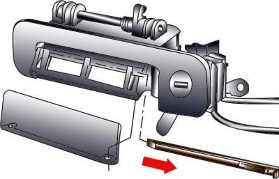
Pic. 16-35. Removing the fixing strip of the door handle trim
Using a small screwdriver, press out the retaining strip of the door handle trim and remove the trim (pic. 16–35).
Installation
Installation is carried out in the reverse order of removal, taking into account the following.
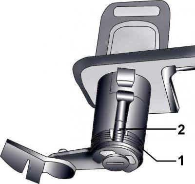
Pic. 16–36. Location of spring ends (1) on both sides of the protrusion of the drive lever (2)
When installing the spring, compress it and place the ends on the left and right side of the drive arm boss (pic. 16–36). Pre-compression of the spring ensures that the actuating lever returns to the middle position.
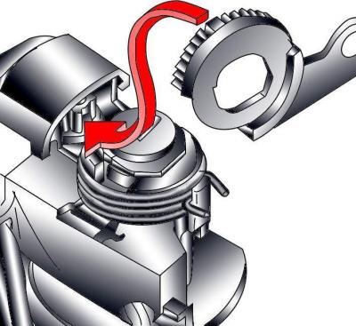
Pic. 16–37. Aligning half of the tooth on the lever with half of the tooth on the microswitch drive gear
Position the drive lever so that half of the tooth on the lever aligns with the half tooth of the microswitch drive gear (pic. 16–37). This ensures the normal functioning of the anti-theft system and the central locking system.
Visitor comments