
Front door handle and lock cylinder
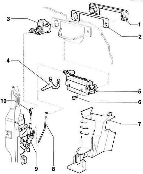
- 1 - visor
- 2 - lining
- 3 - lock cylinder
- 4 - swivel bracket
- 5 - door handle
- 6 - screw, 5 Nm
- 7 - door lock cover
- 8 - safety rod. To remove, disconnect at the drive element –9–.
- 9 - drive element
- 10 - safety rod of the lock cylinder
Front door handle. Models with chassis number from 8L XA 000 001
Warning: The handle shown in the illustration is installed on vehicles with chassis number 8L XA 000 001 and higher.
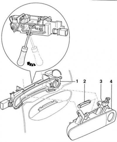
- 1 - handle support. The lock cylinder belongs to the support and cannot be removed separately.
- 2 - locking pin. When installed, the stopper must completely capture the hinge lever.
- 3 - articulated lever
- 4 - door handle
Warning: As of chassis number 8L XA 000 01, a modified lock and handle are installed. Removal of the modified handle is discussed in the subsection Removal and installation the inner wing lining.
Warning: The handle and lock cylinder can be removed separately. To do this, please follow the instructions provided.
Removal
1. Remove the door adjuster holder, refer to subsection Removal and installation the front door and adjusting element holder.
2. Detach cover –7– and remove it from the bottom of the door lock.
3. Disconnect the safety rod –8– at the handle.
4. Disconnect the safety rod –10– at the lock cylinder –3–.
5. Turn the bracket –4– down (against the direction of travel) and remove the lock cylinder.
6. Remove screw –6–.
7. Remove the visor –1–.
8. Remove the lining –2–.
9. Remove the handle –5– from the inside.
Installation
1. Install the visor –1– with the lining –2–.
2. Install the door handle –5– from the inside and press it against the cover plate.
3. Secure the handle with screw –6– to the cover plate.
4. Insert the lock cylinder –3– and secure it with the bracket –4–. To do this, position the bracket at the lock cylinder and tilt it forward (in the direction of movement).
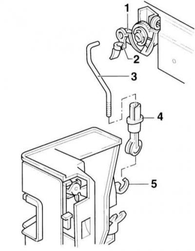
5. Secure the hinge bushing –2– (if she was filming) in the release lever –1– at the lock cylinder.
6. Connect the locking rod –3– of the lock cylinder to the hinge sleeve –2–.
7. Insert the locking rod –3– into the clamp –4–.
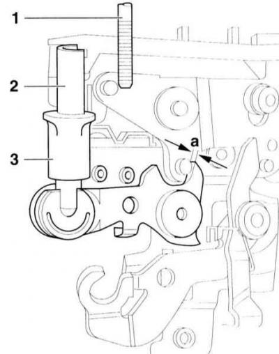
8. Insert the locking rod –1– into the clamp –2– so that the lever –4– has a gap of a = 1 mm.
9. After adjusting the clearance, move the sleeve –3– at the clamp –2– upwards and thus fix the locking rod.
10. Connect the locking rod –8– to the handle –5– (refer to the illustration Front door handle and lock cylinder).
11. Place the cover –7– on the bottom and fix it on top.
12. Insert the holder, refer to the subsection Removal and installation the front door and adjusting element holder.
Removal the handle cover
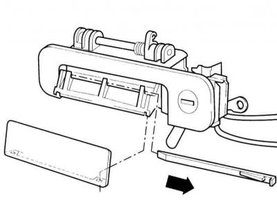
1. Pull the handle up.
2. Use a small screwdriver to pry the locking bar out of the handle in the direction of the arrow and remove the handle.
3. Remove the handle cap from the outside.
Models with chassis number starting from 8L XA 000 001
Removal
1. Remove the door trim and holder.
2. Remove the locking pin –2– and lift up the hinge lever –3–.
3. Use a screwdriver to loosen the bar at the handle support –1–.
4. Remove the handle support and the lock cylinder with the handle.
Installation
Installation is carried out in reverse order.
[The original article is available on the online resource «AUDIMANUAL»]