
Table of contents: Removal ↓ Installation ↓
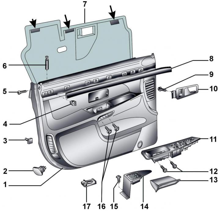
Fig. 16–12. Door trim: 1 – inner door trim; 2 – open door signal lamp; 3 – clamp; 4 – clamp holder; 5 – bolt. 1.7 Nm; 6 – lock button; 7 – protective film (the arrows show the places where it is attached with adhesive tape); 8 – decorative panel; 9 – bolt, 1.8 Nm; 10 – inner door lock opening handle; 11 – Upper section of the overlay with switches; 12 – bolts, 1.8 Nm; 13 – base of the inner door handle; 14 – lower section of the overlay with switches; 15 – screw; 16 – bolts, 4.6 Nm; 17 – lamp for lighting the space when passengers enter and exit
The door trim is shown in Fig. 16–12.
Removal
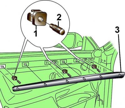
Fig. 16–13. Elements for fastening the decorative panel to the door trim: 1 – retainer holder; 2 – retainer; 3 – decorative panel
Using a screwdriver blade, separate the decorative panel from the door trim as a lever, while the decorative panel fasteners should come out of the holders in the door trim (Fig. 16–13).
Press the clips 2 into the expanding clip holders 1 by about 4 mm and remove the clip holders from the door trim.
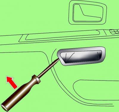
Fig. 16–14. Using a screwdriver to separate the base of the interior door handle from the door trim
Using a screwdriver blade as a lever, separate the base of the inner door handle from the trim and remove it (Fig. 16–14).
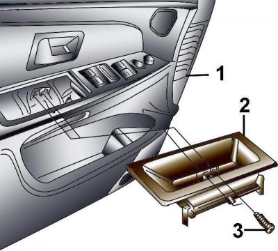
Fig. 16–15. Location of screws (3) for fastening the upper section of the cover with switches (2) to the door trim (1)
Through the opened hole, unscrew the two screws securing the upper section of the overlay with switches (Fig. 16–15).
Lift the rear of the upper section of the switch trim and pull it back to remove the front section from the door trim. Disconnect the electrical connectors from the switches.
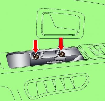
Fig. 16–16. Location of door trim mounting screws
Remove the two screws securing the door trim to the door bracket (Fig. 16–16).
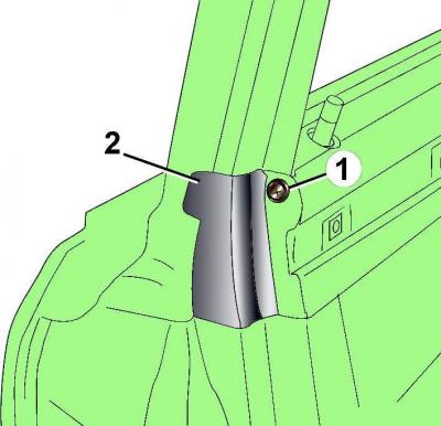
Fig. 16–17. Location of the screw (1) securing the rear insert (2) to the glass frame
Loosen the screw and remove the rear glass frame insert (Fig. 16–17).
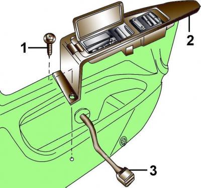
Fig. 16–18. Location of the bolt (1) securing the lower section of the cover with switches (2) and the electrical connector (3)
Loosen the screw and, moving it backwards, remove the lower section of the trim with switches from the door trim (Fig. 16–18).
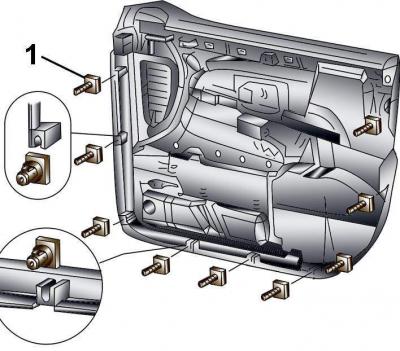
Fig. 16–19. Location of the release clips (1) for fastening the inner door trim
Using a flat fork-shaped tool, separate the trim from the door (Fig. 16–19).
Remove the release clips from the door trim.
By lifting the door trim upwards, remove its upper part from the door lock button.
Tilt the door trim and disconnect the electrical connector from the door lock switch.
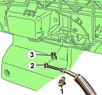
Fig. 16–20. Location of the clamp (1) for fastening the rod (2) of the inner door opening handle and the latch (3) for fastening the inner door opening handle
Using a screwdriver blade as a lever, remove the inner door handle rod mounting clip (Fig. 16–20).
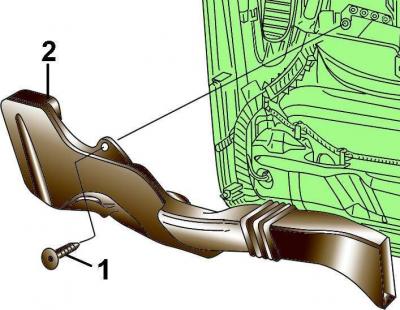
Fig. 16–21. Location of screw (1) securing air duct (2) to door trim
Loosen the screw and remove the air duct from the door trim (Fig. 16–21).
Disconnect all wiring harness fasteners from the door trim and remove the wiring harness.
Remove the protective film from the door.
Installation
Before installing the door trim, check the condition of the trim release clips and replace any damaged clips if necessary. Install the clips into the grooves in the door trim.
The door trim is installed in the reverse order of removal.
Connect the ground wire to the battery.
This article was previously published on the resource Audimanual.ru