
Table of contents: Checking the throttle position… ↓ Checking the operation of the idle… ↓ Checking the throttle potentiometer ↓ Checking the injection nozzle ↓ Checking the forced idle fuel cutoff ↓ Checking temperature sensors ↓ Checking the fuel supply pressure ↓
The following paragraphs describe the procedure for checking the components of the injection system, which can be carried out at home.
Checking the throttle position controller
Disconnect the throttle position controller plug.
Apply a maximum voltage of 6 V to the potentiometer's connecting contacts; positive pole on top.
For a 4-pin plug these are contacts 1 and 2.
For a 6-pin plug, these are contacts 1 and 6.
The required voltage can be obtained from a 4.5-volt battery or a 6-volt charger range.
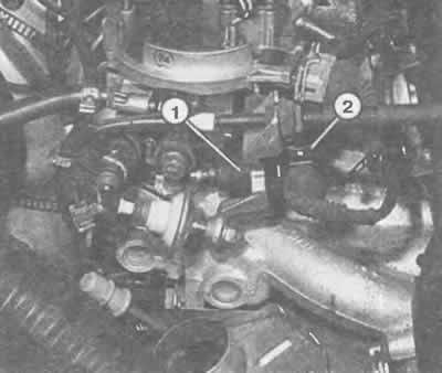
On the fuel mixture preparation unit, in the direction of the vehicle, there is a throttle position regulator (1) with a connecting plug (2).
The plunger should be fully retracted.
Change the pole of the connecting wire (negative contact at the top contact pin).
The plunger should extend fully.
If everything happens as described, then the throttle position controller is OK. If not, it needs to be replaced.
Additionally, you can take resistance measurements.
The resistance of the auxiliary motor winding between the already mentioned connections is 3-200 Ohm.
Checking the operation of the idle speed signal switch
Remove the plug from the throttle position controller.
Connect an ohmmeter to the idle speed signal switch contacts.
For a 4-pin plug these are contacts 3 and 4 (both bottom).
For a 6-pin plug these are contacts 4 and 5 (look down).
If the idle switch is pressed: resistance 0 ohms.
If the idle switch is not pressed: the resistance is infinite.
Note: After replacing the throttle valve, the idle speed switch must be adjusted - this is a workshop job.
Checking the throttle potentiometer
Disconnect the throttle potentiometer plug.
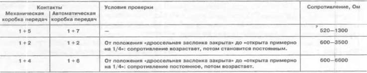
Connect the ohmmeter according to the table (is given on the next page) to two of the four plug contacts.
If the specified values are not achieved, then the throttle potentiometer is faulty. Unfortunately, it is not possible to replace only it. The entire lower part of the fuel mixture preparation unit is always replaced.
Checking the injection nozzle
Check with the engine running: the oil temperature must be at least 60°C, which corresponds to 10 minutes of driving after starting a cold engine.
Remove the air intake pipe.
Start the engine and let it idle.
Monitor the jet of injected fuel. It should be uniform and directed toward the throttle valve.
Turn off the engine to check the valve for leaks.
When the engine is off, no more than two drops should come out per minute.
You will need to perform further checks if the engine does not start.
Check fuses 14, 17 and 19, as well as the fuse in the red holder in the electronics box (Chapter "Body electrical system").
Remove the air filter and air intake pipe.
Turn the engine over with the starter.
The injection nozzle should visibly inject fuel.
If this does not happen, disconnect the brown plug at the top of the fuel mixture preparation unit.
Connect an ohmmeter to both middle connecting contacts (on the fuel mixture preparation unit).
At an ambient temperature between +15° and +30°C, the ohmmeter should show 1.2-1.6 Ohm, otherwise the injector is faulty. Loosen the star-head screw and replace the injector.
Check the power supply to the injection nozzle if it does not work despite the correct resistance readings.
Connect the LED voltmeter, without using any other device, to both middle contacts in the removed plug.
Turn on the starter: the LEDs should flicker, otherwise there is a break in the wiring or a malfunction of the control unit.
Remove the air filter or air intake pipe.
Checking the forced idle fuel cutoff
Start the engine, quickly increase the speed to 3000 rpm, and then quickly close the throttle valve.
The clearly visible injection jet from the injection nozzle should stop briefly at this point. In this case, the fuel supply shutdown in the forced idle mode is OK.
If not, check the throttle position sensor and control unit (in the workshop).
Checking temperature sensors
Inlet Air Temperature Sensor: Disconnect the brown plug from the top of the propellant mixture preparation unit.
Connect an ohmmeter to both outer plug contacts.
Coolant Temperature Sensor: Disconnect the connector on the sensor (blue) in the coolant filler pipe.
Connect an ohmmeter to the sensor contacts.
Both sensors: take resistance readings.
Using the diagram on the next page, you can check whether the resistance values of the sensors, as well as the air and coolant temperatures at the time of measurement, are within the permissible range.
If so, then the sensors are OK.
Checking the fuel supply pressure
Fuel supply pressure can only be accurately controlled by a measuring device used in the workshop.
If you suspect incorrect fuel supply pressure, disassemble the pressure regulator: unscrew the 4 star-head bolts.
Check that the membrane is not damaged and that there are no contaminating deposits.
(The original material is located on the website AUDIMANUAL.RU)