
Repair Chevrolet Repair Toyota Repair Honda Repair AvtoVAZ Repair Mercedes-Benz Repair BMW Repair Opel
Home  |  Contacts  |  Sitemap  |    
English Русский
Български
Беларускі
Український
Српски
Hrvatski
Română
Polski
Slovenský
Magyar
AudiManual.ru


  • AUDI 80
  • AUDI 100
  • AUDI A3
  • AUDI A4
  • AUDI A6
  • AUDI A8
  • AUDI Q
  • OTHER
  • ARTICLES
C4 (1990-1994) C4 (1990-1994, petrol) C3 (1982-1990) C3 (1982-1990, petrol) C3 (1982-1990, diesel)

Mono-Motronic Operating Procedure (Audi 100 C4)

  • Home
  • Audi 100
  • C4 (1990-1994, petrol)
  • Power unit
  • Mono-Motronic injection system
  • Mono-Motronic Operating Procedure
            0
Cold engine starting: The control unit receives information about the engine temperature from the coolant temperature sensor. The colder the engine, the longer the injection period is to create a fuel-rich starting mixture.

Warm-up phase: the temperature sensor reports the gradual warming of the coolant to the control unit through changing resistance values.

Idle: The idle signal switch informs the control unit of this operating mode. The throttle position controller regulates the idle speed and compensates for the reduction in engine speed caused by the activation of powerful current consumers, the power steering fully turned to one side, the automatic transmission in the working position or the air conditioning on.

Normal operation: The control unit receives information about engine operation via speed pulses and resistance readings from the throttle potentiometer (throttle position). From this, the control unit draws conclusions about the engine load status and measures the required amount of fuel to the incoming air through the injection nozzle.

Lambda control: the fuel/air ratio 1=1 is taken into account when dosing the fuel. The constant change of rich and lean mixtures enables optimal operation of the catalytic converter.

Acceleration: Thanks to the signals from the potentiometer, the control unit recognizes a sharp press on the accelerator pedal as an acceleration process, as a result of which the mixture is immediately "enriched". Full load: in the full "gas" position or the control unit ensures enrichment of the combustible mixture in full load mode. Therefore, there is proportionally more fuel in the mixture. The potentiometer informs about the position of the throttle valve. However, when enriching the combustible mixture in full load mode, the signal from the lambda probe is ignored.


Forced idle mode (coasting): The Mono-Motronic injection system saves fuel and shuts off fuel supply as soon as the engine has reached operating temperature. The control unit recognizes this operating condition when the "accelerator" pedal is released (throttle potentiometer), messages from the coolant temperature sensor and engine speed above 1500-1900 rpm.

Engine speed limitation: if the maximum speed is exceeded, the control unit cuts off fuel access. Speed limitation cannot be achieved by turning off the ignition, since unburned fuel will end up in the catalytic converter.
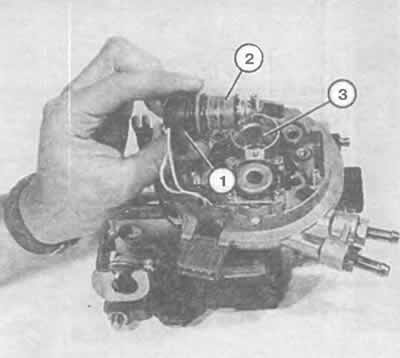
Shown here is the injection nozzle (2) with the plug (1) still connected, removed from the socket…

Shown here is the injection nozzle (2) with the plug (1) still connected, removed from the socket (3) of the fuel mixture preparation unit. The fuel strainer is visible on the side of the valve.
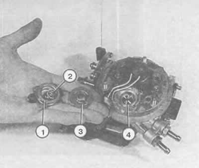

Disassembled pressure regulator. The numbers indicate: 1 — cover; 2 - spring; 3 - membrane; 4 —…

Disassembled pressure regulator. The numbers indicate: 1 — cover; 2 - spring; 3 - membrane; 4 — supporting surface.


Operation in emergency situations: If the signal from one of the information providers does not arrive at all or has a meaningless value, the Mono-Motronic injection system still continues to operate normally. The control unit has so-called reserve values, which are already stored in the memory. Such a reserve value, of course, cannot take into account many operating conditions, but the car still remains mobile. The driver can recognize the absence of a signal from the sensor by insufficient power or poor starting properties.

A link to the original source is available on the website audimanual.ru
The article was checked by auto expert Nikita Rudakov
This article is available at russian, bulgarian, belarusian, ukrainian, serbian, croatian, romanian, polish, slovak, hungarian

Share information:
Previous articles
Audi 100 C4: Mono-Motronic injection system
Next articles

Basic elements
Malfunctions and self-diagnosis
Do-it-yourself repair
Visual inspection
Checking individual elements


Similar articles on other Audi car models:
Electrical diagram of the fuel pump, fuel injection system,… Audi 80 B4 (1991-1996)
Control unit for Motronic, fuel pump relay, injectors... Audi A3 Type 8L (1996-2003)
Operating instructions for quattro cars Audi A4 B5 (1994-2001, petrol)
Electrical diagram of the control unit Motronic, valve… Audi A6 C5 (1997-2004)
Operating principles of the engine management system Audi Q7 Typ 4L (2005-2015, diesel)
Design and operating principle of the steering system Audi A2 (1999-2005)
Link to this page in different formats


Visitor comments

No comments yet


How much will 35 + 48 =


100(C4, 1990-1994) 
  • General information
  • User manual
  • Power unit
  • Engine repair
  • Ignition system
  • Fuel system (gasoline)
  • Fuel system (diesel)
  • Lubrication system
  • Cooling system
  • Exhaust system
  • Transmission
  • Clutch
  • Car gearbox
  • Drive shafts
  • Chassis
  • Car suspension
  • Steering
  • Wheels and tires
  • Brake system
  • Body
  • Ventilation and heating
  • Body repair
  • Electrical equipment
  • Power devices
  • Lighting and appliances
  • Electrical circuits
 
100(C4, 1990-1994, petrol) 
  • General information
  • Operation and maintenance
  • Power unit
  • Engine repair
  • Exhaust system
  • Cooling system
  • Supply system
  • Air filter
  • Mono-Motronic injection system
  • Digifant injection system
  • KE-III-Jetronic and KE-Motronic
  • MPI and MPFI injection system
  • Transmission
  • Clutch
  • Car gearbox
  • Chassis
  • Suspension and steering
  • Brake system
  • Wheels and tires
  • Body
  • Exterior
  • Interior
  • Electrical equipment
  • Fuses and relays
  • Power devices
  • Ignition system
  • Lighting and signaling
  • Equipment and devices
  • Electrical circuits
 
100(C3, 1982-1990) 
  • General information
  • User manual
  • Maintenance
  • Specifications
  • Power unit
  • Engines 4-cylinder
  • Engines 5-cylinder
  • Diesel engine
  • Cooling system
  • Power system (carburetor)
  • Power system (injector)
  • Fuel system (diesel)
  • Transistor ignition system
  • Electronic ignition system
  • Transmission
  • Clutch
  • 4 speed gearbox 014
  • 5 speed gearbox 013 and 093
  • 5 speed gearbox 016 and 012
  • Shift mechanism KP 016
  • Automatic transmission
  • Front wheel drive
  • Chassis
  • Front suspension
  • Rear suspension
  • Steering
  • Brake system
  • Body
  • Body elements
  • Electrical equipment
  • Lighting and appliances
  • Power devices
  • Electrical circuits
 
100(C3, 1982-1990, petrol) 
  • General information
  • Maintenance and operation
  • 4 cylinder engine
  • Engine repair
  • Cooling and lubrication system
  • Supply system
  • Ignition system
  • 5 cylinder engine
  • Engine repair
  • Cooling and lubrication system
  • Supply system
  • Ignition system
  • Transmission
  • Clutch and drive shafts
  • 4 speed gearbox 014
  • 5 speed gearbox 013 and 093
  • 5 speed gearbox 016 and 012
  • Automatic gearbox
  • Chassis
  • Steering
  • Front suspension
  • Rear suspension
  • Brake system
  • Body
  • Body elements
  • Doors, locks and windows
  • Body repair
  • Electrical equipment
  • Equipment and devices
  • Power devices
  • Electrical circuits
 
100(C3, 1982-1990, diesel) 
  • General information
  • User manual
  • Maintenance
  • Troubleshooting
  • Power unit
  • Engine in a car
  • Engine removed
  • Cooling system
  • Fuel system
  • Exhaust system
  • Starting and charging
  • Preheating
  • Transmission
  • Clutch
  • Mechanical gearbox
  • Automatic gearbox
  • Drive shafts
  • Chassis
  • Brake system
  • Suspension
  • Steering
  • Body
  • Exterior
  • Interior
  • Electrical equipment
  • Equipment and devices
  • Electrical circuits
 
AudiManual.ru © 2017-2026 · Mobile version · Feedback · Sitemap: EN BG BY UA RS HR RO PL SK HU · Site search · News and articles
80 B2 · 80 B3 petrol · 80 B3 · 80 B4 · 100 C3 diesel · 100 C3 petrol · 100 C3 · 100 C4 petrol · 100 C4 · A3 Type 8L · A4 B5 petrol · A4 B5 · A4 B6 petrol · A4 B6 · A4 B7 · A4 B8 · A6 C4 · A6 C5 · A6 C5 Allroad · A8 D2 · Q5 Type 8R · Q7 Typ 4L · Audi A2 ·
This site uses cookies 🍪. Click the button to accept this fact.