
Repair Chevrolet Repair Toyota Repair Honda Repair AvtoVAZ Repair Mercedes-Benz Repair BMW Repair Opel
Home  |  Contacts  |  Sitemap  |    
English Русский
Български
Беларускі
Український
Српски
Hrvatski
Română
Polski
Slovenský
Magyar
AudiManual.ru


  • AUDI 80
  • AUDI 100
  • AUDI A3
  • AUDI A4
  • AUDI A6
  • AUDI A8
  • AUDI Q
  • OTHER
  • ARTICLES
C4 (1990-1994) C4 (1990-1994, petrol) C3 (1982-1990) C3 (1982-1990, petrol) C3 (1982-1990, diesel)

Basic elements (Audi 100 C4)

  • Home
  • Audi 100
  • C4 (1990-1994, petrol)
  • Power unit
  • Mono-Motronic injection system
  • Basic elements
            0
Table of contents: Control unit ↓ Throttle valve ↓ Combustible mixture preparation unit ↓ Injection nozzle ↓ Temperature sensor ↓ Pressure regulator ↓ Throttle position controller ↓ Throttle potentiometer ↓

Control unit


It is located in the front passenger footwell area in front of the heating duct and receives information from the following units via a multi-pin plug:

Hall sensor in the ignition distributor - about the engine speed.

Lambda probe in the catalytic converter - about the content of residual oxygen in the exhaust gases.

Potentiometer - about the position of the throttle valve and the amount of incoming air.

The incoming air temperature sensor at the entrance of the combustible mixture preparation unit - about the incoming air temperature.

Temperature sensor on the coolant pipe on the left side of the cylinder head - about the coolant temperature.

By processing the incoming signals, the control unit calculates the duration of the electromagnetic injector opening and thus the amount of fuel injected. In doing so, the control unit uses the multi-parameter characteristics of the engine - a file in which all possible engine states are recorded. Information on the amounts of fuel related to a particular situation is also recorded there in the form of electrical signals. Additionally, the ignition timing indicators related to the amount of fuel and the operating situation are stored in the Mono-Motronic in the form of characteristics.

Throttle valve


It is located at the very bottom of the fuel mixture preparation unit and regulates the amount of air that the engine should receive. The degree of opening of the valve is determined by the driver when pressing the accelerator pedal. The pedal and the throttle valve are directly connected to each other by means of a cable drive of the accelerator.


Combustible mixture preparation unit


Most of the components of the central petrol injection system are assembled in this housing. The incoming air passes through it, and here - via the nozzle - fuel is added, as in the carburetor.

Injection nozzle


It is opened by an electromagnet. Thus, fuel can flow - or not - depending on the signal from the control unit. For optimal fuel atomization, the injector is equipped with beveled outlet holes, through which gasoline enters the conical wall of the outlet hole, swirling there.

The injection nozzle can only open and close, but is not able to dose the amount of fuel. Therefore, it is regulated by the injection time. This is done as follows: the nozzle injects once with each high-voltage current pulse or Hall sensor. If a small amount of fuel is required, the nozzle opens with this pulse only for a short time. If the engine needs more fuel, the injection occurs for a longer time. And so on with each pulse of the Hall sensor.
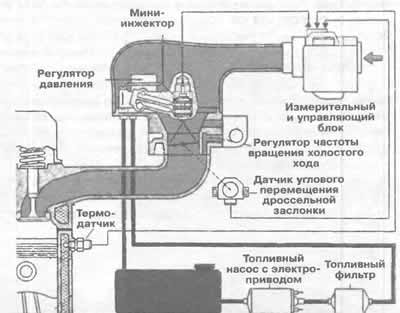
Functional diagram of the Mono-Motronic injection system. The fuel in the system is shown in red,…

Functional diagram of the Mono-Motronic injection system. The fuel in the system is shown in red, and the inlet air is shown in light pink.


Temperature sensor


It is located on the side of the injector body and can thus accurately determine the temperature.

Pressure regulator


The fuel pump supplies gasoline under pressure to the pressure regulator, which ensures that gasoline reaches the injector under the same pressure of 0.8-1.2 bar. It allows some gasoline to flow back into the fuel tank through the drain line. The supply through the fuel filter remains almost constant.

Throttle position controller


A small electric motor with an angular transmission moves the drive tappet closer to or further from the idle stop of the throttle valve. This allows the throttle valve to open more or less depending on the situation. This keeps the idle speed constant under different loads. An idle signal switch is located in the drive tappet of the throttle position controller, which tells the control unit when you release the accelerator pedal.

Throttle potentiometer


It informs the control unit about the movements of the throttle valve and its position. For example, a rapid opening of the throttle valve is recognized as acceleration of the car. If you remove your foot from the accelerator pedal, the throttle valve closing signal activates the cessation of fuel supply in idle mode.
The article was checked by auto expert Nikita Rudakov
This article is available at russian, bulgarian, belarusian, ukrainian, serbian, croatian, romanian, polish, slovak, hungarian

Share information:
Previous articles
Audi 100 C4: Mono-Motronic injection system
Next articles

Mono-Motronic Operating Procedure
Malfunctions and self-diagnosis
Do-it-yourself repair
Visual inspection


Similar articles on other Audi car models:
Basic actions possible with the engine Audi 80 B3 (1986-1991, petrol)
Removal and installation the beam of the adjusting elements and… Audi A3 Type 8L (1996-2003)
Basic information about 6- and 8-cylinder engines Audi A4 B6 (2000-2006)
Elements of the ABS system Audi A6 C4 (1994-1997)
Interior upholstery elements Audi A8 D2 (1994-2002)
Elements outside the cabin, set of elements Audi Q5 Type 8R (2008-2017)
Engine and gearbox mounting elements Audi A2 (1999-2005)
Link to this page in different formats


Visitor comments

No comments yet


How much will 25 + 39 =


100(C4, 1990-1994) 
  • General information
  • User manual
  • Power unit
  • Engine repair
  • Ignition system
  • Fuel system (gasoline)
  • Fuel system (diesel)
  • Lubrication system
  • Cooling system
  • Exhaust system
  • Transmission
  • Clutch
  • Car gearbox
  • Drive shafts
  • Chassis
  • Car suspension
  • Steering
  • Wheels and tires
  • Brake system
  • Body
  • Ventilation and heating
  • Body repair
  • Electrical equipment
  • Power devices
  • Lighting and appliances
  • Electrical circuits
 
100(C4, 1990-1994, petrol) 
  • General information
  • Operation and maintenance
  • Power unit
  • Engine repair
  • Exhaust system
  • Cooling system
  • Supply system
  • Air filter
  • Mono-Motronic injection system
  • Digifant injection system
  • KE-III-Jetronic and KE-Motronic
  • MPI and MPFI injection system
  • Transmission
  • Clutch
  • Car gearbox
  • Chassis
  • Suspension and steering
  • Brake system
  • Wheels and tires
  • Body
  • Exterior
  • Interior
  • Electrical equipment
  • Fuses and relays
  • Power devices
  • Ignition system
  • Lighting and signaling
  • Equipment and devices
  • Electrical circuits
 
100(C3, 1982-1990) 
  • General information
  • User manual
  • Maintenance
  • Specifications
  • Power unit
  • Engines 4-cylinder
  • Engines 5-cylinder
  • Diesel engine
  • Cooling system
  • Power system (carburetor)
  • Power system (injector)
  • Fuel system (diesel)
  • Transistor ignition system
  • Electronic ignition system
  • Transmission
  • Clutch
  • 4 speed gearbox 014
  • 5 speed gearbox 013 and 093
  • 5 speed gearbox 016 and 012
  • Shift mechanism KP 016
  • Automatic transmission
  • Front wheel drive
  • Chassis
  • Front suspension
  • Rear suspension
  • Steering
  • Brake system
  • Body
  • Body elements
  • Electrical equipment
  • Lighting and appliances
  • Power devices
  • Electrical circuits
 
100(C3, 1982-1990, petrol) 
  • General information
  • Maintenance and operation
  • 4 cylinder engine
  • Engine repair
  • Cooling and lubrication system
  • Supply system
  • Ignition system
  • 5 cylinder engine
  • Engine repair
  • Cooling and lubrication system
  • Supply system
  • Ignition system
  • Transmission
  • Clutch and drive shafts
  • 4 speed gearbox 014
  • 5 speed gearbox 013 and 093
  • 5 speed gearbox 016 and 012
  • Automatic gearbox
  • Chassis
  • Steering
  • Front suspension
  • Rear suspension
  • Brake system
  • Body
  • Body elements
  • Doors, locks and windows
  • Body repair
  • Electrical equipment
  • Equipment and devices
  • Power devices
  • Electrical circuits
 
100(C3, 1982-1990, diesel) 
  • General information
  • User manual
  • Maintenance
  • Troubleshooting
  • Power unit
  • Engine in a car
  • Engine removed
  • Cooling system
  • Fuel system
  • Exhaust system
  • Starting and charging
  • Preheating
  • Transmission
  • Clutch
  • Mechanical gearbox
  • Automatic gearbox
  • Drive shafts
  • Chassis
  • Brake system
  • Suspension
  • Steering
  • Body
  • Exterior
  • Interior
  • Electrical equipment
  • Equipment and devices
  • Electrical circuits
 
AudiManual.ru © 2017-2026 · Mobile version · Feedback · Sitemap: EN BG BY UA RS HR RO PL SK HU · Site search · News and articles
80 B2 · 80 B3 petrol · 80 B3 · 80 B4 · 100 C3 diesel · 100 C3 petrol · 100 C3 · 100 C4 petrol · 100 C4 · A3 Type 8L · A4 B5 petrol · A4 B5 · A4 B6 petrol · A4 B6 · A4 B7 · A4 B8 · A6 C4 · A6 C5 · A6 C5 Allroad · A8 D2 · Q5 Type 8R · Q7 Typ 4L · Audi A2 ·
This site uses cookies 🍪. Click the button to accept this fact.