
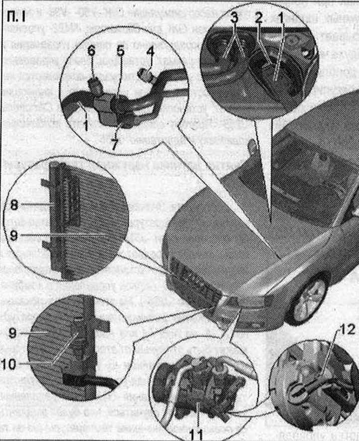
I 1. Refrigerant line with internal heat exchanger. This line contains liquid warm refrigerant (on the pressure side) releases energy to the cold vapor refrigerant (on the low pressure side), thereby increasing the efficiency of the climate control system; 2. Expansion valve. Removal and installation of the refrigerant line with internal heat exchanger; 3. Coolant pipes to the heating heat exchanger in the air conditioner; 4. Service connection in the low pressure circuit for measuring and emptying the refrigerant circuit. Cap with seal, screw tightly. Various executions (with primary seal valve or nipple) depending on the refrigerant line. Depending on the location of the service fitting on the refrigerant line and the vehicle model, it may be necessary to remove the left additional extension reinforcement to connect the service connector of the service station; 5. Low pressure side refrigerant line quick release connection; 6. Service connector in the high pressure circuit for measuring, emptying and charging the refrigerant circuit. Screw the cap and seal carefully. Various executions (with primary seal valve or nipple) depending on the refrigerant line; 7. High pressure side refrigerant line quick release connection; 8. Dryer tank. Remove only when the air conditioning circuit is empty, and take the vehicle to a workshop that has the necessary equipment and trained qualified personnel. The tank is installed directly on the condenser (Removing and installing the dryer tank). Depending on the design of the condenser, the receiver-drier can be installed or built into the condenser; 9. Capacitor. Remove only when the air conditioning circuit is empty, and take the vehicle to a workshop that has the necessary equipment and trained qualified personnel. Various versions (depending on the set car); 10. Refrigerant temperature and pressure sender -G395-. Case color "grey". The coolant temperature and pressure sender -G395- communicates via the bus system "LIN-Bus" with used on-board network -J519-; 11. Air conditioning compressor. Remove the compressor from its mount and install it again (for vehicles with 4-cylinder engine) engine and 6-cyl. TDI engine; 12. Air conditioning compressor control valve -N280-
Visitor comments