Repair Chevrolet Repair Toyota Repair Honda Repair AvtoVAZ Repair Mercedes-Benz Repair BMW Repair Opel
Home  |  Contacts  |  Sitemap  |    
English Русский
Български
Беларускі
Український
Српски
Hrvatski
Română
Polski
Slovenský
Magyar
AudiManual.ru


  • AUDI 80
  • AUDI 100
  • AUDI A3
  • AUDI A4
  • AUDI A6
  • AUDI A8
  • AUDI Q
  • OTHER
  • ARTICLES
C4 (1990-1994) C4 (1990-1994, petrol) C3 (1982-1990) C3 (1982-1990, petrol) C3 (1982-1990, diesel)

Gearbox assembly (Audi 100 C3)

  • Home
  • Audi 100
  • C3 (1982-1990)
  • Transmission
  • 5 speed gearbox 016 and 012
  • Gearbox assembly
            0

Selecting the thickness of the adjusting washer


Size a, mm
Thickness of adjusting washer, mm
8,35–8,64
1,10
8,65–8,94
1,40
8,95–9,24
1,70
9,25–9,54
2,00
9,55–9,84
2,30

Execution order


1. Install the differential assembly into the clutch housing.

2. Install the differential cover and tighten its mounting bolts to a torque of 25 N·m (2.5 kgf·m).

3. Install the axle shaft flanges and tighten their mounting bolts to a torque of 20 N·m (2.0 kgf·m), while securing the flanges from turning.

4. Install axis 23 (see Fig. Gearbox housing type 016) intermediate reverse gear. Install intermediate reverse gear 26, synchronizer 25 and spring 24 on the axle. Before installation, check the axial clearance between the end face of synchronizer 25 and the end face of intermediate reverse gear 26. It should be 0.75–2.30 mm (minimum allowable 0.20 mm). After this, insert plate 22 and secure it to the gearbox housing with bolt 19. Place spring clip 21 on synchronizer pins 25.

5. Insert the secondary shaft together with the 1st and 2nd gear fork rod into the gearbox housing, while pressing the retainer.

6. Insert reverse lock 28 into the gearbox housing.

7. Tighten bolt 5 securing lever 27 for engaging reverse gear.

8. Insert reverse gear engagement lever 27 into the gearbox housing until its threaded sleeve aligns with the bolt, then tighten bolt 5 of the lever mount to a torque of 35 N·m (3.5 kgf·m).

9. Activate reverse gear several times and check the ease of operation of the intermediate reverse gear engagement mechanism.


10. Put the gear into reverse.

11. Install secondary shaft 26 (see Fig. Gearbox type 016) with fork 25 for switching 1st and 2nd gears, rod 22 and link 23 into the gearbox housing.

12. Install the primary shaft into the crankcase together with the fork 28 for switching 3rd and 4th gears, inserted into the groove of the clutch 32 (see fig. 3.25) synchronizer.

13. Install the clamps 5 (see Fig. Gearbox type 016) 3rd and 4th gear shift forks together with pin 20.

15. Secure the forks and leash with spring pins.

16. Install the fork steerer stop bolts with new cardboard washers.

16. Install the fork steerer stop bolts with new cardboard washers.


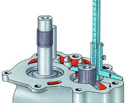
17. Fix the secondary shaft relative to the crankcase and measure dimension a.

18. Select adjusting washer 21 (see Fig. Secondary shaft KP 016) the required thickness and then install it on the shaft (see table. Selecting the thickness of the adjusting washer).

19. Press on gear 22 of the 5th gear of the secondary shaft, having preheated it to a temperature of 120°C. In this case, the flange of the gear should face the bearing.

20. Install washer 23 and tighten bolt 24 into the end of the secondary shaft with a torque of 50 N·m (5.0 kgf·m).


21. Fix the primary shaft relative to the crankcase.

Press on the inner ring 14 (see Fig. Primary shaft KP 016) cylindrical roller bearing, preheating it to a temperature of 120°C. Then install bearing 15.

22. Determine the thickness of the retaining ring 16 so that the axial clearance does not exceed 0.05 mm.

23. Install gear 28 of the 5th gear with the synchronizer clutch, needle bearing 29 with inner ring 30 and fork 36 on the primary shaft (see Fig. Gearbox type 016).

24. Secure the 5th gear engagement fork with spring pin 37.

25. Install retaining ring 27 (see Fig. Primary shaft KP 016).

26. Install the 5th gear synchronizer on the hub.

27. Press hub 25 with a toothed ring onto the primary shaft, having preheated it to a temperature of 120°C.

28. Press on the second inner ring 22 of the bearing.

29. Install gearbox cover 41 together with gasket 40.

30. Press on the first inner ring of the 42 bearing.

31. Install washer 43 and tighten bolt 44 into the end of the primary shaft to a torque of 50 N·m (5.0 kgf·m).

32. Tighten the cover mounting bolts to a torque of 25 N·m (2.5 kgf·m).

33. Install new plug 45.

34. Apply a thin layer of sealant to the mating surfaces of the gearbox and clutch housings and connect them. Tighten the mounting bolts to a torque of 25 N·m (2.5 kgf·m).

35. Apply a thin layer of sealant to the mating surfaces of the clutch housing and cover 16. Install the cover and tighten the bolts 18 for securing it.

35. Apply a thin layer of sealant to the mating surfaces of the clutch housing and cover 16.…


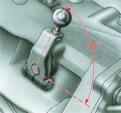
36. Install the gear shift lever, making sure it is installed vertically.

(This article was copied from the website «AudiManual.ru»)
The article was checked by auto expert Daniil Ushakov
This article is available at russian, bulgarian, belarusian, ukrainian, serbian, croatian, romanian, polish, slovak, hungarian

Share information:
Previous articles
Audi 100 C3: 5 speed gearbox 016 and 012
Next articles

Disassembly and assembly of the secondary shaft
Primary shaft
Disassembling the gearbox
Removal and installation the gearbox


Similar articles on other Audi car models:
Disassembly and assembly of the gearbox Audi 80 B2 (1979-1986)
Visual inspection of the gearbox for leaks Audi A3 Type 8L (1996-2003)
Disassembly and assembly of the gearbox Audi A4 B8 (2007-2015)
Gearbox/ final drive Audi A6 C5 (1997-2004)
Visual inspection of gearbox tightness Audi A8 D2 (1994-2002)
Cylinder block from the gearbox side Audi Q5 Type 8R (2008-2017)
Assembly diagram, repair of gear shift lever and gearbox housing Audi A2 (1999-2005)
Link to this page in different formats


Visitor comments

No comments yet


How much will 46 + 26 =


100(C4, 1990-1994) 
  • General information
  • User manual
  • Power unit
  • Engine repair
  • Ignition system
  • Fuel system (gasoline)
  • Fuel system (diesel)
  • Lubrication system
  • Cooling system
  • Exhaust system
  • Transmission
  • Clutch
  • Car gearbox
  • Drive shafts
  • Chassis
  • Car suspension
  • Steering
  • Wheels and tires
  • Brake system
  • Body
  • Ventilation and heating
  • Body repair
  • Electrical equipment
  • Power devices
  • Lighting and appliances
  • Electrical circuits
 
100(C4, 1990-1994, petrol) 
  • General information
  • Operation and maintenance
  • Power unit
  • Engine repair
  • Exhaust system
  • Cooling system
  • Supply system
  • Air filter
  • Mono-Motronic injection system
  • Digifant injection system
  • KE-III-Jetronic and KE-Motronic
  • MPI and MPFI injection system
  • Transmission
  • Clutch
  • Car gearbox
  • Chassis
  • Suspension and steering
  • Brake system
  • Wheels and tires
  • Body
  • Exterior
  • Interior
  • Electrical equipment
  • Fuses and relays
  • Power devices
  • Ignition system
  • Lighting and signaling
  • Equipment and devices
  • Electrical circuits
 
100(C3, 1982-1990) 
  • General information
  • User manual
  • Maintenance
  • Specifications
  • Power unit
  • Engines 4-cylinder
  • Engines 5-cylinder
  • Diesel engine
  • Cooling system
  • Power system (carburetor)
  • Power system (injector)
  • Fuel system (diesel)
  • Transistor ignition system
  • Electronic ignition system
  • Transmission
  • Clutch
  • 4 speed gearbox 014
  • 5 speed gearbox 013 and 093
  • 5 speed gearbox 016 and 012
  • Shift mechanism KP 016
  • Automatic transmission
  • Front wheel drive
  • Chassis
  • Front suspension
  • Rear suspension
  • Steering
  • Brake system
  • Body
  • Body elements
  • Electrical equipment
  • Lighting and appliances
  • Power devices
  • Electrical circuits
 
100(C3, 1982-1990, petrol) 
  • General information
  • Maintenance and operation
  • 4 cylinder engine
  • Engine repair
  • Cooling and lubrication system
  • Supply system
  • Ignition system
  • 5 cylinder engine
  • Engine repair
  • Cooling and lubrication system
  • Supply system
  • Ignition system
  • Transmission
  • Clutch and drive shafts
  • 4 speed gearbox 014
  • 5 speed gearbox 013 and 093
  • 5 speed gearbox 016 and 012
  • Automatic gearbox
  • Chassis
  • Steering
  • Front suspension
  • Rear suspension
  • Brake system
  • Body
  • Body elements
  • Doors, locks and windows
  • Body repair
  • Electrical equipment
  • Equipment and devices
  • Power devices
  • Electrical circuits
 
100(C3, 1982-1990, diesel) 
  • General information
  • User manual
  • Maintenance
  • Troubleshooting
  • Power unit
  • Engine in a car
  • Engine removed
  • Cooling system
  • Fuel system
  • Exhaust system
  • Starting and charging
  • Preheating
  • Transmission
  • Clutch
  • Mechanical gearbox
  • Automatic gearbox
  • Drive shafts
  • Chassis
  • Brake system
  • Suspension
  • Steering
  • Body
  • Exterior
  • Interior
  • Electrical equipment
  • Equipment and devices
  • Electrical circuits
 
AudiManual.ru © 2017-2026 · Mobile version · Feedback · Sitemap: EN BG BY UA RS HR RO PL SK HU · Site search · News and articles
80 B2 · 80 B3 petrol · 80 B3 · 80 B4 · 100 C3 diesel · 100 C3 petrol · 100 C3 · 100 C4 petrol · 100 C4 · A3 Type 8L · A4 B5 petrol · A4 B5 · A4 B6 petrol · A4 B6 · A4 B7 · A4 B8 · A6 C4 · A6 C5 · A6 C5 Allroad · A8 D2 · Q5 Type 8R · Q7 Typ 4L · Audi A2 ·
This site uses cookies 🍪. Click the button to accept this fact.