
Gearbox housing type 013
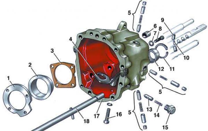
- 1 - locking plate;
- 2 - outer bearing ring;
- 3 - gasket;
- 4 - reverse gear shift lever;
- 5 - retainer;
- 6 - bushing;
- 7 - washer;
- 8 - bolt;
- 9 - locking plunger;
- 10 - locking pin;
- 11 - retaining ring;
- 12 - bearing;
- 13 - retainer bushing;
- 14 - spring;
- 15 - cork;
- 16 - bolt;
- 17 - gearbox housing;
- 18 - reverse gear fork rod
Gearbox cover type 013
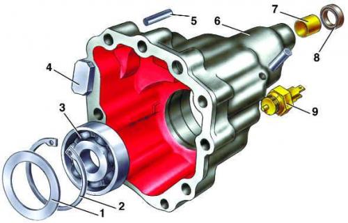
- 1 - gasket;
- 2 - retaining ring;
- 3 - bearing;
- 4 - magnet;
- 5 - pin;
- 6 - gearbox cover;
- 7 - bushing;
- 8 - oil seal;
- 9 - Reverse light switch
Execution order
1. Install outer ring 3 (see Fig. Secondary shaft of the gearbox type 013) the front roller bearing of the secondary shaft and secure it on the 013 type gearbox with pin 2, and on the 093 type gearbox with a bolt with an internal hexagon.
2. Install the clamps 5 (see Fig. Gearbox housing type 013), locking plungers 9 and locking pin 10 of the gear shift fork rods if they were removed.
3. Install into crankcase 12 (see Fig. Gearbox type 013) gearbox secondary shaft 39 with fork 42 and rod 41 for switching 1st and 2nd gears.
4. Install intermediate gear 45 for reverse gear on axle 36 and press it into gearbox housing 12.
5. Install primary shaft 46 into gearbox housing 12, engaging the gears of the primary and secondary shafts.
6. Install fork 43 for switching 3rd and 4th gears into the groove of the synchronizer clutch, insert the rod into the fork hole and fix the fork on the rod with pin 44.
7. Set all gear shift fork rods to neutral position.
8. Press on the second inner ring 38 of the rear double-row tapered roller bearing of the secondary shaft 39.
9. Install washer 15 on primary shaft 46 with the protruding part towards the gearbox housing.
10. Heat to 120°C and press on the inner ring 16 of the 5th gear needle bearing until it stops, using a suitable mandrel.
11. Heat to 120°C and press gear 34 of the 5th gear onto secondary shaft 39 until it stops.
12. Install both rows of needle bearing 17 on the input shaft.
13. Install gear 18 of 5th gear with synchronizer and fork 20 for engaging 5th gear on primary shaft 46.
14. Secure fork 20 to the rod with pin 19.
15. Heat to 120°C and install hub 22 with toothed rim until it stops.
16. Press the inner ring of the rear bearing onto the primary shaft.
17. Attach gearbox housing 12 to clutch housing 8, installing gasket 10 between them and tighten mounting bolts 13 to a torque of 25 N·m (2.5 kgf·m).
18. Engage one of the gears and secure the input shaft from turning.
19. Tighten nut 33 on the end of the secondary shaft to a torque of 100 N·m (10.0 kgf·m) and lock it.
20. Install the leash 32 on the 1st and 2nd gear shift fork rod.
21. Move back the 35 fork shift rod for 3rd and 4th gears, thereby engaging 3rd gear.
22. Insert gear shifter 30 into the gearbox housing and insert the leg of the shifter rod into the groove of the 3rd and 4th gear fork rod.
23. Secure the leash 32 to the 1st and 2nd gear shift fork rod with a pin.
24. Set all gear shift fork rods to neutral position.
25. Install cover 6 (see Fig. Gearbox cover type 013) gearbox with gasket 23 (see Fig. Gearbox type 013) and tighten the 28 fastening bolts with a torque of 25 N·m (2.5 kgf·m), having first applied a layer of sealant to the threads.
26. Tighten bolt 26 at the end of the primary shaft to a torque of 45 N·m (4.5 kgf·m) and install a new plug 27.
Warning: When replacing the secondary shaft rear bearing, secondary shaft, gearbox and clutch housings, and differential, it is necessary to adjust the secondary shaft pinion and the final drive side clearance and the differential bearing preload. These operations require the use of special equipment and tooling, so it is recommended that they be performed at a service station.