



Table of contents: Disassembly ↓ Assembly ↓
Primary shaft of the gearbox type 013
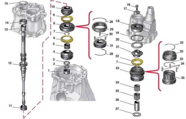
- 1 - needle bearing;
- 2 - retaining ring;
- 3 - thrust washer;
- 4 - 4th gear pinion;
- 5 - 4th gear needle bearing;
- 6 - synchronizer locking ring;
- 7 - synchronizer retaining ring;
- 8 - synchronizer;
- 9 - synchronizer locking ring;
- 10 - 3rd gear pinion;
- 11 - 3rd gear needle bearing;
- 12 - primary shaft;
- 13 - inner bearing ring;
- 14 - bearing;
- 15 - retaining ring;
- 16 - bolt;
- 17 - washer;
- 18 - bearing;
- 19 - retaining ring;
- 20 - gasket;
- 21 - hub with toothed ring;
- 22 - 5th gear synchronizer locking ring;
- 23 - 5th gear pinion with synchronizer;
- 24, 25 - 5th gear needle bearing;
- 26 - inner ring of 5th gear needle bearing;
- 27 - washer;
- 28 - spring;
- 29 - coupling;
- 30 - cracker;
- 31 - hub;
- 32 - spring;
- 33 - coupling;
- 34 - cracker;
- 35 - 5th gear pinion with hub
Disassembly
1. Remove retaining ring 2 and thrust washer 3.
2. Remove gear 4 of 4th gear and needle bearing 5, marking it.
3. Remove retaining ring 7.
4. Mark the position of the clutch and synchronizer hub relative to the shaft.
5. Press synchronizer 8 together with blocking rings 6 and 9 and gear 10 of 3rd gear (applying force to the 3rd gear).
6. Remove needle bearing 11 of 3rd gear and mark it.
7. Press the inner ring of the middle bearing off the shaft.
Assembly
1. Press the inner ring of the middle bearing onto the shaft.
2. Install needle bearing 11 of the 3rd gear on the primary shaft, having previously lubricated it with transmission oil.
3. Install gear 10 of 3rd gear.
4. Install the synchronizer of 3rd and 4th gears in assembly with blocking rings in accordance with the previously made marks. (Disassembly and assembly of the synchronizer are described in subsection 7.4.1.4). In this case, the gap between the 5th gear pinion and the blocking ring should be 1.0–1.9 mm (minimum allowable gap 0.5 mm). Otherwise, the locking ring must be replaced.
5. Install retaining ring 7.
6. Install needle bearing 5 and gear 4 of 4th gear on the shaft.
7. Install thrust washer 3 and retaining ring 2.
8. Using a feeler gauge, check the axial clearance between the 4th gear pinion and the thrust washer, which should be 0.10–0.40 mm. If the clearance does not correspond to the specified one, select a new thrust washer 3 of the required thickness and replace it. Spare parts are supplied with thrust washers with a thickness of 3.47; 3.57 and 3.67 mm.
(The original text of the material can be found on the website: «AUDIMANUAL.ru»)