Repair Chevrolet Repair Toyota Repair Honda Repair AvtoVAZ Repair Mercedes-Benz Repair BMW Repair Opel
Home  |  Contacts  |  Sitemap  |    
English Русский
Български
Беларускі
Український
Српски
Hrvatski
Română
Polski
Slovenský
Magyar
AudiManual.ru


  • AUDI 80
  • AUDI 100
  • AUDI A3
  • AUDI A4
  • AUDI A6
  • AUDI A8
  • AUDI Q
  • OTHER
  • ARTICLES
C4 (1990-1994) C4 (1990-1994, petrol) C3 (1982-1990) C3 (1982-1990, petrol) C3 (1982-1990, diesel)

Disassembling the gearbox (Audi 100 C3)

  • Home
  • Audi 100
  • C3 (1982-1990)
  • Transmission
  • 5 speed gearbox 016 and 012
  • Disassembling the gearbox
            0

Gearbox housing type 016


Gearbox housing type 016

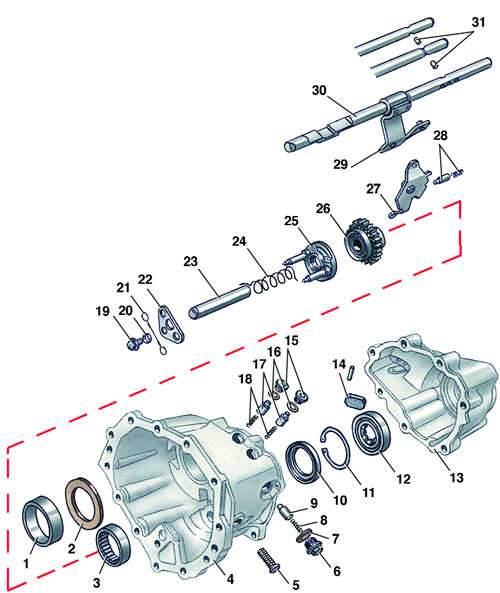
  • 1 - outer bearing ring;
  • 2 - adjusting ring;
  • 3 - bearing;
  • 4 - gearbox housing;
  • 5 - bolt;
  • 6 - retainer plug;
  • 7 - gasket;
  • 8 - spring;
  • 9 - retaining sleeve;
  • 10 - thrust plate;
  • 11 - retaining ring;
  • 12 - bearing;
  • 13 - crankcase cover;
  • 14 - magnet;
  • 15 - cork;
  • 16 - gasket;
  • 17 - retaining sleeve;
  • 18 - spring;
  • 19 - bolt;
  • 20 - washer;
  • 21 - spring clip;
  • 22 - mounting plate;
  • 23 - reverse gear axle;
  • 24 - spring;
  • 25 - reverse gear synchronizer;
  • 26 - reverse intermediate gear;
  • 27 - reverse gear lever;
  • 28 - reverse lock;
  • 29 - Reverse gear fork;
  • 30 - activation rod;
  • 31 - pin

Execution order


1. Clean the gearbox from dirt and wash the outside.

2. Unscrew the oil filler and drain plugs and drain the oil from the gearbox if this has not been done previously.

3. Loosen the mounting screw and remove the lever from the gear shift rod.

4. Unscrew three bolts 18 (see Fig. Gearbox type 016) and remove cover 16 with gasket.

5. Remove the 14-speed shifter assembly from the clutch housing.

6. Loosen the bolts 2 for fastening and disconnect the gearbox housing 1 from the clutch housing 7.

7. Knock out plug 45 from gearbox cover 41 using a suitable tool.


8. Secure the primary shaft 19 from turning using the splines and unscrew bolt 44 from the opposite end of the primary shaft.

9. Clamp the gearbox housing 52 in a vice.

10. Loosen the mounting bolts and remove cover 41 of the gearbox, pressing off the inner ring of the rear bearing of the primary shaft.

11. Press the second inner ring 39 of the rear bearing off the primary shaft.

12. Press hub 46 with the 5th gear ring gear.

13. Knock out pin 37 of the 5th gear fork.

14. Remove retaining ring 27 (see Fig. Primary shaft KP 016).

15. Remove gear 4 (see fig. Gearbox type 016) 5th gear with synchronizer and fork for engaging 36 5th gear.

16. Remove two rows of needle bearing 49.

17. Loosen the limiting bolts 29 of the fork rods

18. Engage one of the gears and secure the primary shaft from turning. Unscrew bolt 35 from the end of the secondary shaft.

19. Press gear 33 of the 5th gear off the secondary shaft and remove adjusting washer 32 of gear 33 of the 5th gear.

20. Knock out spring pin 24 from link 23 of the 1st and 2nd gear shift rod, placing a support under the rod so as not to damage the hole in the crankcase.

21. Knock out pin 27 from fork 28 for switching 3rd and 4th gears, placing a support under the rod so as not to damage the hole in the crankcase.

22. Remove the 3rd and 4th gear shift fork rod 21 from the crankcase.

23. Unscrew plug 15 (see Fig. Gearbox housing type 016) and remove retainer 17 with spring 18 from the crankcase.

24. Unscrew bolt 51 (see fig. Gearbox type 016) fastenings of the intermediate lever 53 for engaging reverse gear.


25. Extend the primary 19 and secondary 26 shafts as far as possible from the gearbox housing and remove the primary shaft 19 together with the fork 28 for switching 3rd and 4th gears.

26. Remove the reverse gear lock by moving the intermediate lever 53 for engaging the reverse gear to the side.

27. Remove secondary shaft 26 with rod 22 of fork 25 for switching 1st and 2nd gears.

28. Remove spring clip 21 (see Fig. Gearbox housing type 016) reverse synchronizer and unscrew bolt 19 securing plate 22.

29. Remove plate 22 and axle 23 with spring 24, synchronizer 25 and intermediate reverse gear 26 from the crankcase.

30. Unscrew the speedometer drive gear.

31. Unscrew bolt 3 (see fig. Gearbox housing type 016) fastening flange 12 of the axle shaft, fixing the flange through the holes for the fastening bolts using a rod or punch.

32. Loosen bolts 13 securing differential cover 11.

33. Remove differential cover 11 with sealing ring using two screwdrivers.

34. Remove differential 10 assembly from the clutch housing.
The article was checked by auto expert Daniil Ushakov
This article is available at russian, bulgarian, belarusian, ukrainian, serbian, croatian, romanian, polish, slovak, hungarian

Share information:
Previous articles
Audi 100 C3: 5 speed gearbox 016 and 012
Next articles

Removal and installation the gearbox
The device of a five-speed gearbox
Primary shaft
Disassembly and assembly of the secondary shaft
Gearbox assembly


Similar articles on other Audi car models:
General description of the mechanical gearbox Audi 80 B3 (1986-1991, petrol)
Visual inspection of the gearbox for leaks Audi A3 Type 8L (1996-2003)
Gearbox and final drive Audi A4 B5 (1994-2001, petrol)
Gearbox/ final drive Audi A6 C5 (1997-2004)
Visual inspection of gearbox tightness Audi A8 D2 (1994-2002)
Cylinder block from the gearbox side Audi Q5 Type 8R (2008-2017)
Fastening the gearbox to the engine Audi A2 (1999-2005)
Link to this page in different formats


Visitor comments

No comments yet


How much will 20 + 29 =


100(C4, 1990-1994) 
  • General information
  • User manual
  • Power unit
  • Engine repair
  • Ignition system
  • Fuel system (gasoline)
  • Fuel system (diesel)
  • Lubrication system
  • Cooling system
  • Exhaust system
  • Transmission
  • Clutch
  • Car gearbox
  • Drive shafts
  • Chassis
  • Car suspension
  • Steering
  • Wheels and tires
  • Brake system
  • Body
  • Ventilation and heating
  • Body repair
  • Electrical equipment
  • Power devices
  • Lighting and appliances
  • Electrical circuits
 
100(C4, 1990-1994, petrol) 
  • General information
  • Operation and maintenance
  • Power unit
  • Engine repair
  • Exhaust system
  • Cooling system
  • Supply system
  • Air filter
  • Mono-Motronic injection system
  • Digifant injection system
  • KE-III-Jetronic and KE-Motronic
  • MPI and MPFI injection system
  • Transmission
  • Clutch
  • Car gearbox
  • Chassis
  • Suspension and steering
  • Brake system
  • Wheels and tires
  • Body
  • Exterior
  • Interior
  • Electrical equipment
  • Fuses and relays
  • Power devices
  • Ignition system
  • Lighting and signaling
  • Equipment and devices
  • Electrical circuits
 
100(C3, 1982-1990) 
  • General information
  • User manual
  • Maintenance
  • Specifications
  • Power unit
  • Engines 4-cylinder
  • Engines 5-cylinder
  • Diesel engine
  • Cooling system
  • Power system (carburetor)
  • Power system (injector)
  • Fuel system (diesel)
  • Transistor ignition system
  • Electronic ignition system
  • Transmission
  • Clutch
  • 4 speed gearbox 014
  • 5 speed gearbox 013 and 093
  • 5 speed gearbox 016 and 012
  • Shift mechanism KP 016
  • Automatic transmission
  • Front wheel drive
  • Chassis
  • Front suspension
  • Rear suspension
  • Steering
  • Brake system
  • Body
  • Body elements
  • Electrical equipment
  • Lighting and appliances
  • Power devices
  • Electrical circuits
 
100(C3, 1982-1990, petrol) 
  • General information
  • Maintenance and operation
  • 4 cylinder engine
  • Engine repair
  • Cooling and lubrication system
  • Supply system
  • Ignition system
  • 5 cylinder engine
  • Engine repair
  • Cooling and lubrication system
  • Supply system
  • Ignition system
  • Transmission
  • Clutch and drive shafts
  • 4 speed gearbox 014
  • 5 speed gearbox 013 and 093
  • 5 speed gearbox 016 and 012
  • Automatic gearbox
  • Chassis
  • Steering
  • Front suspension
  • Rear suspension
  • Brake system
  • Body
  • Body elements
  • Doors, locks and windows
  • Body repair
  • Electrical equipment
  • Equipment and devices
  • Power devices
  • Electrical circuits
 
100(C3, 1982-1990, diesel) 
  • General information
  • User manual
  • Maintenance
  • Troubleshooting
  • Power unit
  • Engine in a car
  • Engine removed
  • Cooling system
  • Fuel system
  • Exhaust system
  • Starting and charging
  • Preheating
  • Transmission
  • Clutch
  • Mechanical gearbox
  • Automatic gearbox
  • Drive shafts
  • Chassis
  • Brake system
  • Suspension
  • Steering
  • Body
  • Exterior
  • Interior
  • Electrical equipment
  • Equipment and devices
  • Electrical circuits
 
AudiManual.ru © 2017-2026 · Mobile version · Feedback · Sitemap: EN BG BY UA RS HR RO PL SK HU · Site search · News and articles
80 B2 · 80 B3 petrol · 80 B3 · 80 B4 · 100 C3 diesel · 100 C3 petrol · 100 C3 · 100 C4 petrol · 100 C4 · A3 Type 8L · A4 B5 petrol · A4 B5 · A4 B6 petrol · A4 B6 · A4 B7 · A4 B8 · A6 C4 · A6 C5 · A6 C5 Allroad · A8 D2 · Q5 Type 8R · Q7 Typ 4L · Audi A2 ·
This site uses cookies 🍪. Click the button to accept this fact.