
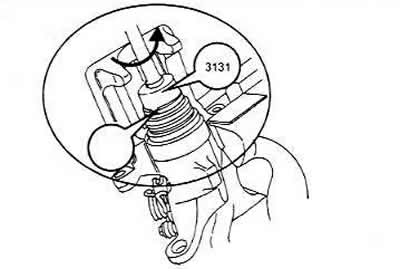
Checking the thickness of brake linings
As a rule, a change in the thickness of the brake pads by 1 mm corresponds to a vehicle mileage of at least 1,000 km. However, this rule is only valid under unfavorable operating conditions. Under normal conditions, the pads last much longer. Shine a flashlight through the hole in the wheel disk onto the caliper. You can even remove the rear wheel to see the brake pads better. When the brake pad thickness is 7 mm, the wear limit has been reached and the pads need to be replaced. During this measurement, the rear plate of the pad is also measured. This measurement is performed in the same way as described earlier for the front wheel brake.
Replacing brake pads
If the brake pads are reinstalled, they need to be marked to match their previous position. Although the clamps look the same as on early Audi models, the pistons have been modified and a special tool is now needed to ensure that the pistons are self-extending (through the adjustment mechanism) screw it back into the hole before inserting the new brake pads. The pistons have two opposite grooves into which the trunnion key is installed. If you don't have one, you can use a steel strip the same width as the piston and the width of the groove for screwing in.
Raise the rear of the car on stands and remove the wheel.
Unscrew the lower hex bolt of the cylinder body with a spanner, holding the guide pin by the hex with an open-end wrench as shown in the figure. If you do not hold the hex, the guide pin will turn and destroy the fastening. Naturally, the open-end wrench must be thin enough to be inserted into the gap. Unscrew the fastening bolt at the top in the same way.
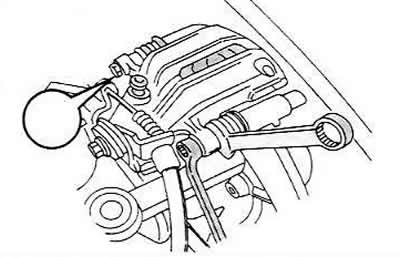
Raise the cylinder body and secure it together with the hose in a suitable manner to the rear suspension parts.
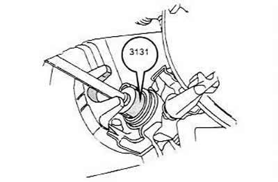
The brake pads are now free and can be removed after being marked (if they are reused).
Clean the guide surfaces or the housing bore with compressed air if available, or with a rag if not. Never inhale the dust blown out by the brake pads. Do not use mineral-based solvents or sharp-edged tools. Check the protective cap at the end of the piston; hardened caps must be replaced. Before installing the brake pads, check the brake disc. If there are deep scratches, remove the brake disc and regrind it or replace it. The section "Brake Disc Treatment" contains instructions on this matter.
When installing brake pads, proceed as follows:
Screw the piston into the caliper cylinder using the special trunnion key mentioned above. Apply pressure to the inner side.
The next section will give you instructions on how to unscrew the piston without a tool. Before pressing in, remove some brake fluid from the reservoir, otherwise the fluid may leak out of the reservoir and damage the paint. Brake fluid is poisonous! Never suck the fluid out with your mouth through a hose, but use a bulb or something similar. Collect the fluid in a bottle.
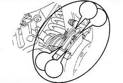
Insert the brake shoes. It may be necessary to push the piston further. Make sure the shoes are seated correctly in the positions shown by the arrows before reinstalling the cylinder body.
Install the cylinder body on the brake disc and secure with new self-locking bolts. Tightening torque is 30 Nm. Each brake pad repair kit contains new bolts for each brake caliper.
Note: The bolts used to secure the rear caliper carrier are tightened to a torque of 95 Nm (ribbed bolts) or 6Nm (allen bolts).
Now you can set the brakes to the basic (initial) position, i.e. check the parking brake adjustment.
Lower the vehicle to the ground and tighten the wheel nuts.
Add brake fluid to the reservoir.
Press the brake pedal several times so that the brake pads fit correctly on the disc. New pads need to be run in, i.e. at the beginning of their use, you need to brake carefully.
Brake caliper repair
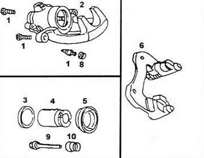
Rear brake caliper components
1 Self-locking bolts 3Nm
2 Brake caliper housing
3 Cylinder sealing ring (cuff)
4 Piston with regulator, diameter 38 mm
5 Dust cap
6 Brake caliper carrier
7 Screw (valve) for air removal
8 Dust cap
9 Guide pin (finger)
10 Rubber cuff
Clamp the cylinder in a vice with soft jaws and first thoroughly clean it with brake fluid or alcohol. Unscrew the parking brake cable retainer mounting bolts.
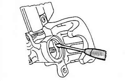
Using a special key, unscrew the piston from the caliper. Install the key's projections into the piston recess shown by the arrow.
There is a similar notch on the other side. If you use a piece of steel strip the same width as the piston and the thickness suitable for the notch, you can also use it to turn out the piston. Do not damage the edges of the notch.
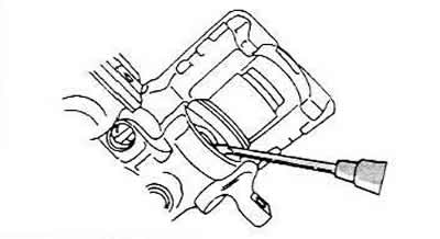
Using a screwdriver, carefully remove the sealing ring (cuff) from the inside of the cylinder bore.
Clean all parts thoroughly if the cylinder is in good condition and use the parts from the repair kit during assembly. If the caliper carrier is replaced, install it, having lubricated it, on the guide pins. Replace the carrier or replace the protective cuffs, using the repair kit, if the protective cuffs or guide pins are damaged.
Lubricate the new sealing ring (cuff) with brake fluid or special grease and insert it into the groove.
Carefully press the inner sealing lips of the dust ring into the cylinder groove using a screwdriver.
Install the special key mentioned above or a steel strip into the piston and screw the piston inward. Apply uniform force to the piston while screwing it in. When the piston is seated, the outer sealing edges of the dust ring will enter the groove of the piston.
Lubricate the bleed valve with special brake grease and tighten it. The brake caliper must first be bleeded. To do this, attach the bleed hose to the bleed valve and attach the other end of the hose to a syringe filled with brake fluid. You can use a rubber bulb, which should be well cleaned beforehand. Inject brake fluid until it comes out of the brake hose hole without air bubbles.
Now the caliper is ready for installation.