Repair Chevrolet Repair Toyota Repair Honda Repair AvtoVAZ Repair Mercedes-Benz Repair BMW Repair Opel
Home  |  Contacts  |  Sitemap  |    
English Русский
Български
Беларускі
Український
Српски
Hrvatski
Română
Polski
Slovenský
Magyar
AudiManual.ru


  • AUDI 80
  • AUDI 100
  • AUDI A3
  • AUDI A4
  • AUDI A6
  • AUDI A8
  • AUDI Q
  • OTHER
  • ARTICLES
C4 (1990-1994) C4 (1990-1994, petrol) C3 (1982-1990) C3 (1982-1990, petrol) C3 (1982-1990, diesel)

Brake booster (Audi 100 C4)

  • Home
  • Audi 100
  • C4 (1990-1994)
  • Chassis
  • Brake system
  • Brake booster
            0
The brake booster cannot be repaired. If damage is found, it must be replaced.

A failure of the brake booster does not mean a loss of braking efficiency, it only means that the pedal force required to achieve the same braking efficiency increases.

The brake booster receives the vacuum required for its operation via the vacuum line from the intake manifold. The functionality of the brake booster can be checked as follows:

With the engine off, press the brake pedal several times until all vacuum is released from the system.

Press the pedal with medium force and start the engine.

If the brake booster is working properly, the brake pedal will noticeably drop. The brake booster cannot be removed by simple means, as it is necessary to use special tools used by Audi to separate the brake pedal from the push rod. Only if these tools are available can the following description be read.

Remove the trim from the driver's side.

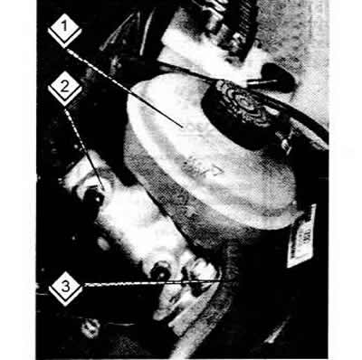
Remove the brake fluid reservoir as described above. To do this, remove the clutch hydraulic system hose (3), the plug connection (2) and the reservoir (1). The reservoir must be removed by rocking it back and forth.

Remove the brake fluid reservoir as described above. To do this, remove the clutch hydraulic system…


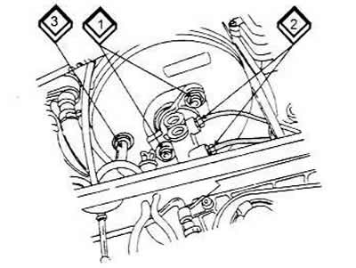
The following steps should be carried out using the figure below as a guide.


First, you need to disconnect both brake pipes (2), pull them out and carefully bend them to the side. Wipe off the leaking brake fluid with a rag. Disconnect the vacuum hose (3) from the brake booster on the side. Now unscrew the mounting bolts (1). For this, you need a Torx T45 head with an extension.

First, you need to disconnect both brake pipes (2), pull them out and carefully bend them to the…


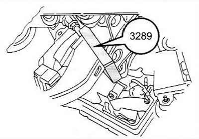
Next, the brake booster pushrod is disconnected from the pedal, which is associated with the difficulties already mentioned. First, remove the brake light switch. If a cruise control system is installed (cruise control), then you need to remove the air inlet valve nearby. The switch and valve must be installed in a certain way.

Now install special tool #3289 on the pedal. The brake booster push rod is removed from the pedal. Pull the brake pedal back to complete the removal.

Remove the brake booster together with the master cylinder from the housing.

Remove the brake booster together with the master cylinder from the housing.


Note: The master brake cylinder can also be removed in advance, as described above. In this case, unscrew the two flange nuts.


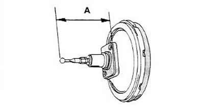
Installation is carried out in the reverse order of removal. If a new brake booster is to be installed, the length of the pushrod must be readjusted. In this case, the distance between the mounting surface of the brake booster and the end of the pushrod, marked as (A), is measured. Since the pushrod can move, care must be taken to ensure that it is perpendicular to the booster. In addition, there should be no gasket present when measuring. If it is stuck, its thickness must be taken into account when measuring.

To adjust, loosen the lock nut and move the push rod. After adjustment, tighten the lock nut.

To adjust, loosen the lock nut and move the push rod. After adjustment, tighten the lock nut.


Replace the gasket and re-tighten the brake booster. The bolts do not need to be replaced.

Lightly lubricate the pivot pin and reconnect the brake pedal/push rod connection.

If the brake cylinder has been removed, replace the flange nuts (50 Nm). Tighten the union nuts of the pipes to 15 Nm.

The check valve located in the brake booster may be the cause of the system malfunction. To check, you can carefully push out the valve with a screwdriver and blow it in the direction of the arrow on the valve. Air should come out on the other side. If you blow from the other side, the air should not come out. When replacing the valve, you must select the same one that was there before. The valve is pressed into the brake booster.
The article was checked by auto expert Georgy Rodionov
This article is available at russian, bulgarian, belarusian, ukrainian, serbian, croatian, romanian, polish, slovak, hungarian

Share information:
Previous articles
Audi 100 C4: Brake system
Next articles

Main brake cylinder
Removal the brake drum
Measuring drum brake shoes
Rear drum brakes
Removal air from the brake system («bleeding»)
Parking (hand) brake
Anti-lock braking system (ABS)


Similar articles on other Audi car models:
Checking the brake booster Audi 80 B2 (1979-1986)
Checking the brake booster Audi A3 Type 8L (1996-2003)
Brake booster — general information Audi A4 B5 (1994-2001, petrol)
Checking the brake booster Audi A6 C5 (1997-2004)
Parking brake Audi A8 D2 (1994-2002)
Disconnecting and connecting the brake pedal and brake booster Audi Q5 Type 8R (2008-2017)
Brake pads — thickness check Audi A2 (1999-2005)
Link to this page in different formats


Visitor comments

No comments yet


How much will 31 + 26 =


100(C4, 1990-1994) 
  • General information
  • User manual
  • Power unit
  • Engine repair
  • Ignition system
  • Fuel system (gasoline)
  • Fuel system (diesel)
  • Lubrication system
  • Cooling system
  • Exhaust system
  • Transmission
  • Clutch
  • Car gearbox
  • Drive shafts
  • Chassis
  • Car suspension
  • Steering
  • Wheels and tires
  • Brake system
  • Body
  • Ventilation and heating
  • Body repair
  • Electrical equipment
  • Power devices
  • Lighting and appliances
  • Electrical circuits
 
100(C4, 1990-1994, petrol) 
  • General information
  • Operation and maintenance
  • Power unit
  • Engine repair
  • Exhaust system
  • Cooling system
  • Supply system
  • Air filter
  • Mono-Motronic injection system
  • Digifant injection system
  • KE-III-Jetronic and KE-Motronic
  • MPI and MPFI injection system
  • Transmission
  • Clutch
  • Car gearbox
  • Chassis
  • Suspension and steering
  • Brake system
  • Wheels and tires
  • Body
  • Exterior
  • Interior
  • Electrical equipment
  • Fuses and relays
  • Power devices
  • Ignition system
  • Lighting and signaling
  • Equipment and devices
  • Electrical circuits
 
100(C3, 1982-1990) 
  • General information
  • User manual
  • Maintenance
  • Specifications
  • Power unit
  • Engines 4-cylinder
  • Engines 5-cylinder
  • Diesel engine
  • Cooling system
  • Power system (carburetor)
  • Power system (injector)
  • Fuel system (diesel)
  • Transistor ignition system
  • Electronic ignition system
  • Transmission
  • Clutch
  • 4 speed gearbox 014
  • 5 speed gearbox 013 and 093
  • 5 speed gearbox 016 and 012
  • Shift mechanism KP 016
  • Automatic transmission
  • Front wheel drive
  • Chassis
  • Front suspension
  • Rear suspension
  • Steering
  • Brake system
  • Body
  • Body elements
  • Electrical equipment
  • Lighting and appliances
  • Power devices
  • Electrical circuits
 
100(C3, 1982-1990, petrol) 
  • General information
  • Maintenance and operation
  • 4 cylinder engine
  • Engine repair
  • Cooling and lubrication system
  • Supply system
  • Ignition system
  • 5 cylinder engine
  • Engine repair
  • Cooling and lubrication system
  • Supply system
  • Ignition system
  • Transmission
  • Clutch and drive shafts
  • 4 speed gearbox 014
  • 5 speed gearbox 013 and 093
  • 5 speed gearbox 016 and 012
  • Automatic gearbox
  • Chassis
  • Steering
  • Front suspension
  • Rear suspension
  • Brake system
  • Body
  • Body elements
  • Doors, locks and windows
  • Body repair
  • Electrical equipment
  • Equipment and devices
  • Power devices
  • Electrical circuits
 
100(C3, 1982-1990, diesel) 
  • General information
  • User manual
  • Maintenance
  • Troubleshooting
  • Power unit
  • Engine in a car
  • Engine removed
  • Cooling system
  • Fuel system
  • Exhaust system
  • Starting and charging
  • Preheating
  • Transmission
  • Clutch
  • Mechanical gearbox
  • Automatic gearbox
  • Drive shafts
  • Chassis
  • Brake system
  • Suspension
  • Steering
  • Body
  • Exterior
  • Interior
  • Electrical equipment
  • Equipment and devices
  • Electrical circuits
 
AudiManual.ru © 2017-2026 · Mobile version · Feedback · Sitemap: EN BG BY UA RS HR RO PL SK HU · Site search · News and articles
80 B2 · 80 B3 petrol · 80 B3 · 80 B4 · 100 C3 diesel · 100 C3 petrol · 100 C3 · 100 C4 petrol · 100 C4 · A3 Type 8L · A4 B5 petrol · A4 B5 · A4 B6 petrol · A4 B6 · A4 B7 · A4 B8 · A6 C4 · A6 C5 · A6 C5 Allroad · A8 D2 · Q5 Type 8R · Q7 Typ 4L · Audi A2 ·
This site uses cookies 🍪. Click the button to accept this fact.