
Table of contents: Checking the condition of the brake… ↓ Removal brake pads ↓ Removal the brake cylinder of a drum… ↓
The brake drum can be removed after the wheel has been removed.
Unscrew the wheel bolts.
Support the car from behind.
Turn the wheel rim or brake drum so that the wheel bolt hole is at the front and top.
Press the adjusting key upwards with a screwdriver through the wheel bolt hole - this will compress the brake pads.
Remove the wheel bearing grease cap.
Straighten the wheel bearing retaining pin and pull it out.
Tighten the crown lock. Loosen the hex nut, remove the thrust washer and outer wheel bearing.
Pull off the brake drum.
When assembling, adjust the wheel bearing play.
Press the brake shoes against the drum several times by pressing hard on the brake pedal.
Caution. If the rusted adjusting key on older cars does not press down, ask an assistant to press the brake pedal while simultaneously pressing the key up. Release the brake pedal and remove the screwdriver from the brake drum, otherwise the key will slide down. Note that the pedal should only be pressed when both brake drums are being installed.
Checking the condition of the brake drums
The sliding surface of the brake drum should be as smooth as possible.
If deep grooves and notches are found (due to the brake pads being worn down to the rivets), then the drum can be re-ground.
After regrinding, the inner diameter of the drum must exceed the nominal diameter by 1 mm, otherwise both brake drums must be replaced.
For reground brake drums, thicker brake shoes must be used.
Removal brake pads
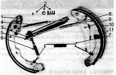
Disassembled drum brake components
1 Front brake shoe
2 Holder with spring plate and locking pin
3 Push bar
4 Upper spring
5 Adjusting key
6 Tension spring
7 Lower return spring
8 Adjacent spring
9 Parking brake lever
10 Brake lining on the rear brake shoe
11 Holder. Arrows indicate where the springs are attached during installation
Remove the brake drum.
Turn the spring plate 90° with pliers, pressing it lightly (holding the locking pin on the rear shield of the brake mechanism from turning) and remove it together with the spring. Unhook the return spring of the adjusting key.
Remove the brake shoes from the lower support and the pistons of the wheel brake cylinder. Disconnect the return spring of the adjusting key.
Remove the brake shoes from the lower support and the pistons of the wheel brake cylinder. Disconnect the parking brake cable from the parking brake lever.
Remove the upper and lower return springs. Pull the adjusting key out of the pressure rod.
Unhook the adjacent spring from the top of the pressure rod. If necessary, clamp the pressure rod in a vice for this purpose.
When assembling, clamp the pressure rod in a vice. Attach the adjacent spring to the pressure rod and brake shoe.
Install the brake shoe onto the pressure rod. Insert the adjusting key from above. Its nose should point towards the brake shoe.
Insert the secondary (rear) brake shoe lever into the recess of the pressure rod, attach the upper return spring.
Attach the parking brake cable to the brake lever with the brake shoes not yet installed.
Removal the brake cylinder of a drum brake
Remove the brake drum.
Remove the brake pads.
Unscrew the air bleed valve. Unscrew the brake pipe. Since the new brake cylinder will not be installed immediately, you need to press the brake pedal and hold it to avoid unnecessary fluid loss.
Unscrew the two mounting bolts at the rear of the brake mechanism shield and remove the cylinder.