
Table of contents: Removal and installation the master… ↓ Repair of the main brake cylinder ↓ Brake fluid level control device ↓
All the cars of the described models are equipped with a dual-cavity master brake cylinder, equipped with a dual reservoir for brake fluid. So both circuits of the dual-circuit brake system can be supplied with brake fluid.
The main brake cylinder cannot be repaired, i.e. if the cylinder fails, it must be replaced with a new one. The brake pipes are divided diagonally, i.e. two pistons work with two circuits as follows:
The piston closest to the push rod operates the left front brake and the right rear brake, while the intermediate piston operates the right front brake and the left rear brake.
Attention: If it is suddenly discovered that the force required for braking increases or the braking distance is lengthened, this means that one of the brake circuits has failed.
Removal and installation the master brake cylinder
The master cylinder is mounted on the front surface of the brake booster and can be removed from the engine compartment.
Before starting work, press the brake pedal several times to remove the vacuum from the brake booster. If there is no vacuum, then plug the vacuum line on the booster.
Suck the brake fluid out of the reservoir, then remove the mesh. To remove the fluid, use a bulb or syringe, but never by mouth.
Remove the check indicator plug from the tank.
Remove the hose going to the clutch cylinder.
Pull the reservoir out of the brake cylinder, rocking it back and forth.
Note: This will cause the remaining brake fluid to spill out and you will need to prepare a rag to collect it.
Unscrew the brake pipe connections and bend the pipes to the side. Mark the installation location of each pipe.
Unscrew the cylinder nuts (only two nuts, not bolts). The rubber seal is located at the end of the brake booster.
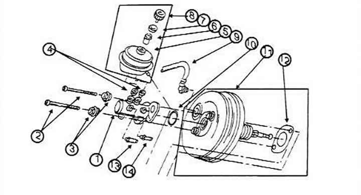
Mounting elements of the master brake cylinder and brake booster
1 Master brake cylinder
2 Torx bolt, 25 Nm
3 Flange nut, 50 Nm (new)
4 Sealing sleeve
5 Brake fluid cans (the coupling connection is on the side shown)
6 Grid
7 Sealing ring.
8 Cork
9 Vacuum pipeline
10 Always replace the sealing ring after removing the cylinder
11 Brake booster
12 Gasket (glued)
13 Pipeline for the intermediate port circuit
14 Piston 1 circuit line. The dashed lines indicate the attachment points on the engine compartment bulkhead
The cylinder is installed in the reverse order of removal. Tighten both flange nuts (3) to 50 Nm, and the union nuts of the brake pipes to 15 Nm. There is no need to adjust the brake booster push rod (only when replacing the amplifier). In this case, it is necessary to adjust the length of the push rod to a certain length.
Lubricate the sealing bushings in the cylinder with brake fluid and press the brake fluid reservoir onto the bushings. The bushings must be in good condition. Finally, fill the system with brake fluid and bleed the clutch and brake hydraulic system as described in the relevant sections.
Repair of the main brake cylinder
The brake master cylinder of the models covered in this manual cannot be repaired. The brake master cylinder and brake booster may be supplied by different manufacturers, but it does not matter which product is installed when the cylinder needs to be replaced. The same applies to the brake booster.
The rubber bushings (4) for the reservoir can be replaced. if moisture is visible in this area. Press the reservoir carefully to the right and left, inserting a screwdriver, which will allow you to squeeze out the rubber bushings. Lubricate the new rubber bushings with brake fluid and press them into the master cylinder. Then carefully insert the reservoir. Remove air from the brake system.
Brake fluid level control device
The control lamp on the instrument panel lights up and the buzzer starts to sound when something is wrong with the brake fluid level. To check, remove the plug (8), turn on the ignition and press your finger on the grid (6). The control lamp should light up and the buzzer should sound. If this happens, the control device is working properly.
(This article was copied from the website: audimanual)