



Table of contents: Checking brake linings ↓ Replacing brake pads ↓
Checking brake linings
The brake pad wear indicator lamp signals that the thickness of the remaining brake pad material needs to be measured. Brake pads should have a service life of approximately 5,000 km, i.e. no further checking is performed when the mileage approaches this value. As a rule, a decrease in the lining thickness by 1 mm corresponds to a vehicle mileage of at least 10,000 km, and even then under unfavorable operating conditions. Under normal conditions, the mileage is much greater, i.e. the linings last longer.
For a quick check, which should be done regularly, it is necessary to shine a flashlight through the hole in the wheel disk into the brake caliper. For a more detailed check, remove the wheel so that you can see the pad better. When the pad thickness is 7 mm, the wear limit has been reached and the pads need to be changed. When checking, the thickness of the base plate is also measured. Its thickness is 5 mm, i.e. the remaining lining is 2.0 mm thick.
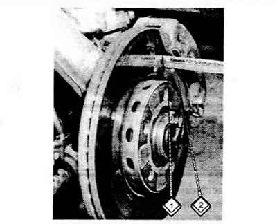
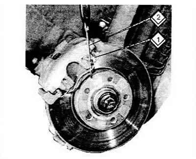
The thickness of the brake lining is measured between the edge of the metal plate (2) and the brake disc (1).
Replacing brake pads
This work should only be carried out if you have some experience in working with brakes, as traffic safety depends on it.
Audi models are equipped with two different designs of brake calipers. Both are described in this section. These designs can be identified by the markings on the brake caliper. ATE (Teves) brake calipers have the "ATE" designation and the Audi emblem (4 rings). ATE also uses Allen-head bolts, which are covered with rubber caps.
Caution: Replace brake pads only as a set. Also, never swap pads from one side to the other to even out possible wear. It is important to note that only parts recommended by the manufacturer should be used.
Brakes by Girling
Pull the cylinder body outward by hand. This will push the pistons back. Before doing this, you need to remove some brake fluid from the brake fluid reservoir, because the fluid may leak out and cause damage. This will definitely happen when the reservoir is filled to the brim with fluid. Brake fluid is poisonous! You cannot suck it out with your mouth through a hose, you need to use a bulb syringe or a medical syringe. The fluid must be drained into a special container.
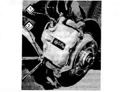
Remove the lower hexagonal bolt of the cylinder body (2). To do this, hold the guide pin on the inside with an open-end wrench so that you can unscrew the bolt with a spanner. Unscrew only the lower bolt, do not loosen the upper bolt (1) under any circumstances. It must be replaced if it becomes unreliable.
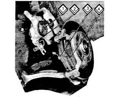
Fold back the cylinder (caliper) housing (2) and pull out the brake pads (3 and 4). Remove the heat shields from the pads (1). Be sure to pay attention to how they are installed so that you can position them in the same way later.
Clean the guide planes or the housing seat with compressed air if possible, or a rag if not. Do not use mineral solvents or sharp-edged tools. Check that the protective cap and clamping ring are seated correctly. Replace damaged, brittle or hardened protective caps. Check the brake disc before installing the brake pads. If there are deep dents or scratches, remove the brake disc and regrind it, or replace it.
Install the heat shields in their old position on the pistons (when using new casings, install the same ones).
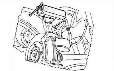
Install the brake pads. You may have to push the pistons further. There is a special clamp for this, which is shown in the picture. If there is no clamp (he visits service stations), then you can push the pistons in with a piece of wood. In doing so, you need to make sure that the brake fluid does not spill out of the reservoir.
Fold the cylinder body down (so that it doesn't hit the pads) and secure it with new self-locking bolts, holding the guide pins with an open-end wrench as described above. The tightening torque is 30 Nm. It should be noted that the open-end wrench should not be too wide. This could mean that the wrench will be clamped without achieving the required tightening torque. The open-end wrench should, of course, be replaced with a socket wrench with a torque wrench. New bolts are included with each Audi repair kit for replacing the brake pads. These bolts must always be replaced. The repair kit also contains two heat shields.
After installation, press the brake pedal hard several times to bring the pads into working position relative to the disc.
Check and adjust the brake fluid level in the reservoir. Remember that at the beginning of work the pads must "grind in", so during this period you need to brake carefully.
Disc brakes from ATE (Teves)
The front brake pads are checked for wear in the same way as described above for Girling brakes. If the brake pads are to be refitted, they must be marked where they were attached (inside or outside).
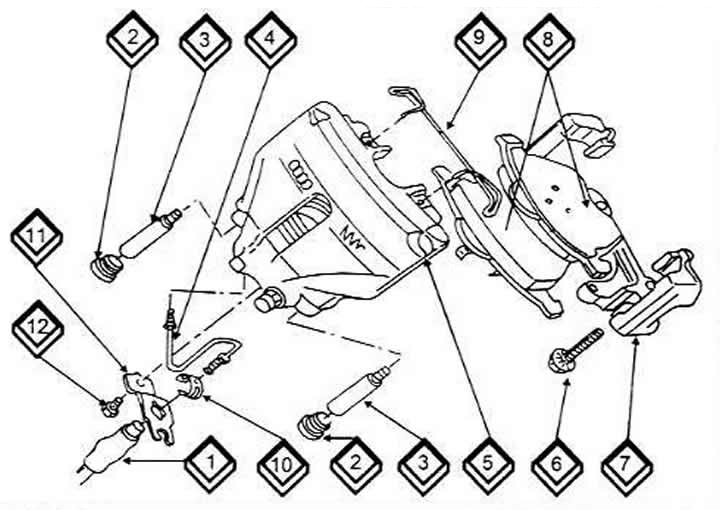
1 Brake hose
2 Bolt Protector Caps
3 Guide pins, 25 Nm
4 Brake pipe
5 Brake caliper cylinder
6 Ribbed bolt, 125 Nm
7 Caliper support
8 Brake pads
9 Fastening spring
10 Bracket for fastening spring
11 Hose mounting bracket
12 Bolt
Remove both front wheels.
Insert a screwdriver (2) into the mounting spring (1) and unhook it from the mounting in the brake caliper housing.
Remove the protective caps, shown by the arrows, from the guide pins to gain access to the bolt (pin) heads.
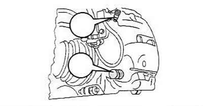
After unscrewing the Allen bolts, remove the brake caliper.
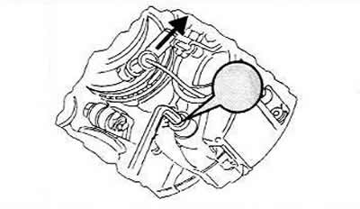
Raise the caliper and secure it with a piece of wire in a suitable place. Do not allow the caliper to hang on the hose.
Remove the brake pads to the right and left of the brake disc. Pull the inner pad out of the piston together with the mounting clamp. Remove the outer pad from the caliper. Sometimes it "sticks" tightly. In this case, pry it off with a screwdriver. Clean the guide surfaces or the area in the housing bore, if possible, with compressed air, or with a rag if there is none. Do not use mineral solvents or sharp-edged tools. Check that the protective cap and clamping ring are seated correctly. Replace damaged, brittle or hardened protective caps. Check the brake disc before installing the brake pads. If there are deep dents or scratches, remove the brake disc and regrind it or replace it.
When installing brake pads, proceed as follows:
Remove any remaining adhesive foil from the contact surface of the outer shoe.
Push the piston into the hole. Usually a clamp is used to do this, with the help of which the piston is pressed. If the brake fluid reservoir is full, it may overflow. To avoid this, it is necessary to remove the fluid from the reservoir.
Install the brake pads. The outer brake pads on the metal plate are covered with adhesive film. It must be removed without leaving any residue. When installing, do not damage the adhesive layer on the metal plate. The inner brake pad is installed in the piston with a mounting bracket.
Carefully install the brake caliper onto the brake pads and brake disc and screw in the two bolts. The screwed-in Allen bolts (use old bolts) tighten them one by one until a tightening torque of 25 Nm is reached. This means that you need to have a straight (not curved) allen key to use a torque wrench. If the wrench shown in the picture is used, the tightening torque must be estimated "by eye".
Press the brake pedal several times to bring the brake pads into working position relative to the brake disc.
At first, you need to brake carefully so that the pads can "grind" to the disc.