
Each wheel has a wheel speed sensor that measures the rotational speed of the wheel. The sensor consists of a magnetic core and winding and is installed at a certain distance from the toothed rotor. The rotors for the front wheels are mounted on the outer CV joints of the drive shafts, the rotors for the rear wheels are mounted on the hubs. When the hub rotates, the magnetic field of the sensor changes, causing an alternating voltage, the frequency of which changes depending on the speed of the wheel.
The signals from the sensors are sent to an electronic control unit that can accurately determine whether the wheel is accelerating or decelerating relative to the recommended speed. The information from the electronic control unit is sent to a hydraulic modulator that contains four traction relays, each acting on one valve for one brake, all of which operate independently of each other in three different modes:
Pressure increase stage:The solenoid inlet valves are open, brake pressure from the master cylinder is applied directly to the brake calipers.
Constant pressure stage: The solenoid inlet and outlet valves are closed, the brake system pressure in the calipers is maintained at a constant level, even if the master cylinder pressure increases.
Pressure reduction stage:The solenoid inlet valve is closed to prevent further brake system pressure from reaching the caliper and, in addition, the outlet valve is opened to relieve existing pressure and release the brake. Fluid returns to the master cylinder through the return, pumping the hydraulic modulator.
The braking cycle is described for one wheel, the systems of all four wheels work in a similar way, although independently.
The wheel speed is measured by wheel speed sensors and processed by the electronic control unit. By comparing the signals received from each wheel, the control unit can determine the recommended speed and detect any deviation from this speed that could lock the brake. If locking is detected, the control unit switches to the constant pressure stage, and no further increase in pressure in the brake system will affect this brake. If locking is still present, the pressure reduction stage is switched on to unlock the wheel. The control unit again switches to the constant pressure stage until the wheel speed increases to a certain value, then the cycle is repeated, the control unit again switches to the pressure increase stage. This control cycle is continuously and quickly repeated until the brake pedal is released or the vehicle stops.
An additional circuit in the electronic control unit monitors the system's operation and alerts the driver to damage via a warning light. If damage occurs, the system must be switched off, allowing normal braking without ABS.
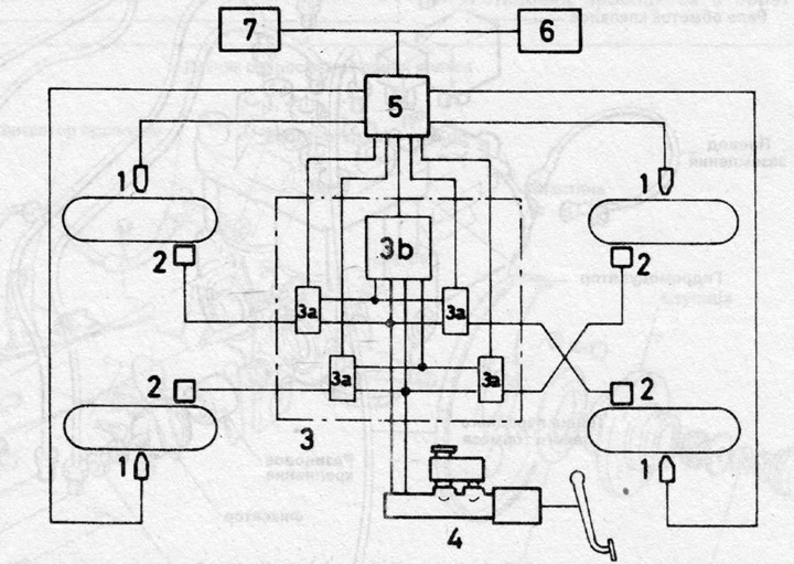
Fig. 9.38 Schematic layout of the anti-lock braking system (Chapter 27)
1 - Wheel speed sensors
2 - Brake calipers
3 - Hydraulic modulator
3a - Solenoid valves
3b - Return pump
4 — Master brake cylinder
5 — Electronic control device
6 — Control lamp
7 — ABS switch