Table of contents: Hydraulic modulator ↓ Electronic control device ↓
Note: Before starting work, see. Chapter 28.
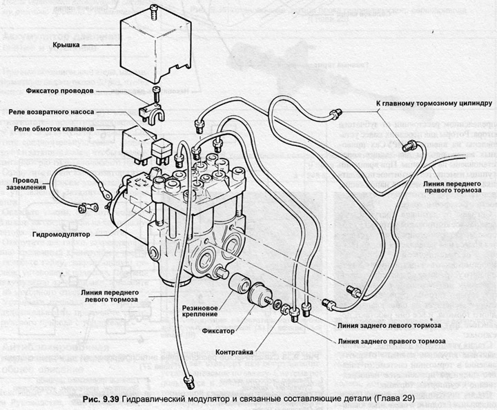
Hydraulic modulator
1. Disconnect the battery ground clamp.
2. Remove the modulator control relay by unscrewing the screw and lifting the plastic cover. The large relay controls the solenoid valve, the small relay controls the return pump. Installation is done in reverse order.
3. To remove the modulator unit, remove the relay cover, unscrew the cable terminal, disconnect the modulator wiring. Disconnect the ground wiring on the modulator body.
4. Unscrew the brake pipe couplings, remove the pipe and immediately plug its end and the modulator hole.
5. Unscrew the mounting nuts of the modulator and the clamps, remove the unit. Do not disassemble the modulator, this unit is in a non-separable housing and cannot be repaired.
6. Installation is carried out in the reverse order. Bleed the hydraulic system as described in Chapters 17 and 28.
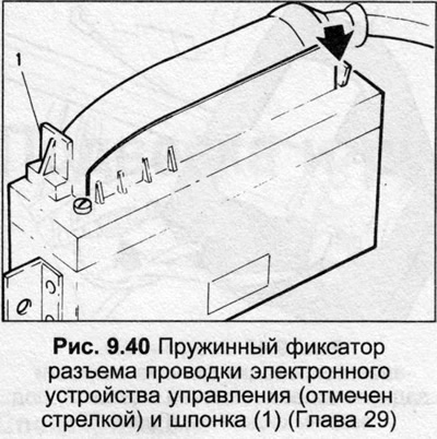
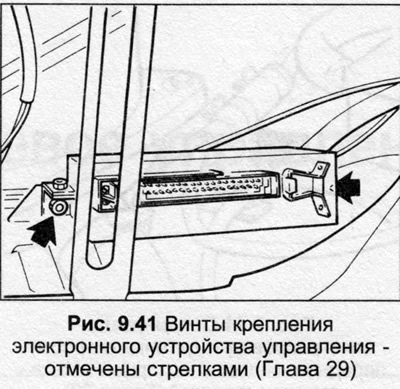
Electronic control device
7. Disconnect the battery ground clamp.
8. Remove the rear seat. The control unit is located under the seat on the left side.
9. Disconnect the control unit connector.
10. Unscrew the lock nuts and remove the control unit.
11. Installation is carried out in reverse order.
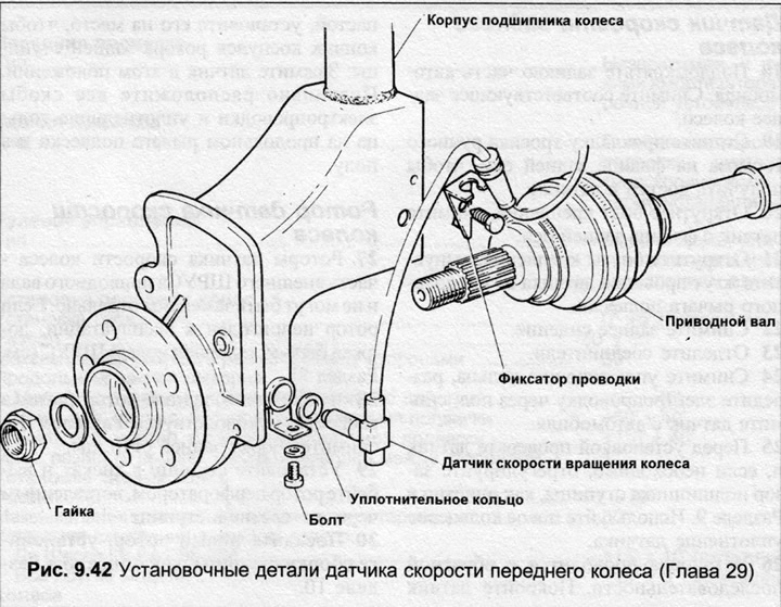
Front wheel speed sensor
12. Jack up the front of the car. Remove the corresponding front wheel.
13. Unscrew the mounting bolt and remove the sensor from the front suspension strut.
14. Release the cable sealing rings from the brackets on the suspension strut and below the wheel.
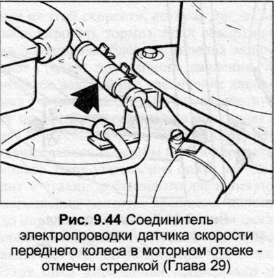
15. From inside the engine compartment, release the wiring connector from the bracket, separate the connector. The left connector is located behind the radiator expansion tank, the right connector is located behind the windshield washer reservoir.
16. Route the wiring through the wheel arch, remove the speed sensor assembly.
17. Installation is carried out in the reverse order. When installing, carefully move the sensor towards the rack as far as possible so that the tip touches the CV joint rotor. Clamp the sensor in this.
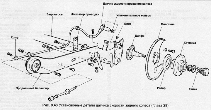
Rear wheel speed sensor
18. Jack up the rear of the vehicle. Remove the corresponding rear wheel.
19. Pull the handbrake cable routing off the rear axle flange to access the sensor.
20. Unscrew the mounting bolt and remove the sensor from the rear axle flange.
21. Unscrew the mounting bolts and release the sensor wiring harness from the suspension trailing arm.
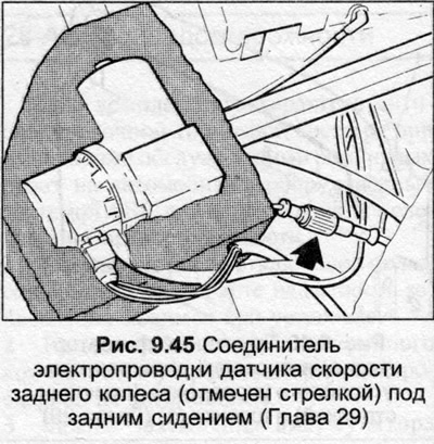
22. Remove the rear seat.
23. Separate the connectors.
24. Remove the sealing rings, route the electrical wiring through the floor, and remove the sensor from the vehicle.
25. Before installation, check the sensor and, if necessary, adjust the hub bearing clearance as described in Section 10. Use a new sensor O-ring.
26. Installation is carried out in the reverse order. Cover the sensor with paste, install it in place so that the tip touches the rear hub rotor. Clamp the sensor in this position. Correctly position all electrical wiring clips and sealing rings on the trailing arm and in the floor.
Wheel speed sensor rotor
27. The wheel speed sensor rotors are part of the outer CV joint of the drive shaft and cannot be replaced separately. If the rotor is not serviceable, a new CV joint must be installed (see Section 8).
28. To remove the rear rotor of the speed sensor, refer to Section 10, remove the rear hub assembly.
29. Place the hub in a vice and knock out the rotor with a punch inserted through the hole in the hub.
30. Install the new rotor, install the hub assembly as described in Section 10.