
Table of contents: Functioning of the electric fan of… ↓ Fan thermal switch switching… ↓
The Audi 100 is equipped with different cooling system fans depending on the engine type.
Models with 4- and 6-cylinder engines have an electrically driven fan that only kicks in if the coolant temperature rises too high. A 6-cylinder engine usually has two separate fans.
In a 5-cylinder engine it is different. There is a so-called fan with a viscous coupling. It is not connected electrically. When the temperature inside the radiator rises, the power clutch between the pulley, the torque to which is transmitted from the engine via a belt drive, and the working disk of the fan (impeller) is achieved by means of liquid (Visco) coupling.
Separate from the main fan, the so-called additional blow-off fan operates after the engine has stopped: an additional electric fan blows out the stagnant hot air from the engine compartment of the 5-cylinder engine after the car has stopped. The same thing happens in the 4-cylinder engine with a power of 85 kW, but due to the already existing fan with an electric drive.
In certain vehicle equipment options (for example, with a factory-fitted towing hitch or on vehicles with a reinforced cooling system, as well as in some 6-cylinder engines) an additional electric fan is installed next to the already mentioned cooling system fan.
On 5-cylinder models, there is no room for a second cooling fan. Therefore, when a towbar or air conditioning is installed at the factory, a more powerful 300-watt fan motor is used to provide additional purge fan functions in place of the regular 50-watt fan motor for additional cooling (via thermal switch).
Functioning of the electric fan of the cooling system. 4- and 6-cylinder engine
You will find the electrical connection diagrams in the chapter "Electrical diagrams". Separately in serial versions, the matter looks like this:
A temperature-sensitive switch is screwed into the radiator. If it "senses" that the liquid flowing past it after passing the radiator is still hot (more than 92°C), it switches on the fan via the relay on the plug cell 2 on the relay stand 1 - the central switch (rear left in the engine compartment). It is located in the relay control circuit and determines when the contacts that switch the electric current from terminal 30 should be closed (constantly under tension) to the fan.
The control circuit itself receives current from terminal X only when the ignition is on, so the relay contacts can only be closed in the ignition on position.
In the same way, it switches off the electric fan if the temperature at the bottom of the radiator drops below 84°C.
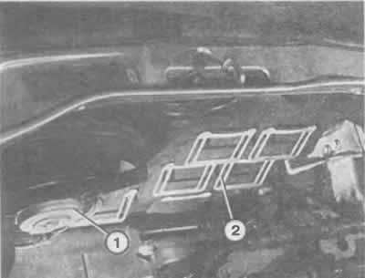
The illustration shows the fans of a 4-cylinder engine with a reinforced cooling system. It functions as follows: the actual cooling fan (2) drives the second cooling fan (1) via a small V-belt.
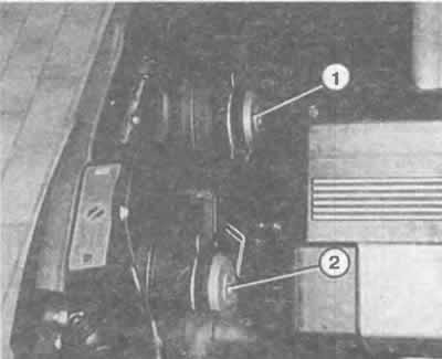
With a 6-cylinder engine, a two-speed fan is installed in place of such a design. Cars with an enhanced cooling system are equipped with two two-speed fans, each with its own drive.
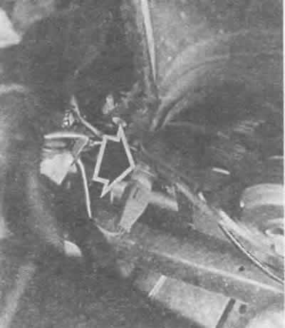
The cooling fan thermal switch in vehicles with 4-cylinder and 6-cylinder engines is installed on the radiator at the bottom left.
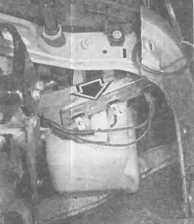
Additional resistors for the two-speed cooling fan are located slightly below the left headlight. The arrow in the illustration indicates the resistor board with the shock absorber removed.
If the water temperature in the lower part of the radiator has risen by more than 99°C, then the second stage of the thermal switch starts to operate, switching the second stage of the fan speed through cell 3 (on the relay stand 1). The shutdown occurs as in the previous case.
Fan thermal switch switching temperatures

Additional fan activation 4-cylinder 85 kW and 5-cylinder engines
In models with a 4-cylinder 85 kW engine and a 5-cylinder engine, the cooling system is supplemented by a so-called sequential fan.
This system functions as follows: if hot air stagnates in the engine compartment after the engine has stopped, the cooling system fan provides access to cold air. This prevents the formation of vapor locks in the high-pressure fuel lines - the cause of problems starting a hot engine. In this circuit, the thermal switch on the cylinder head "feels" the temperature in the cylinder head and turns on the fan via the control unit for turning on the cooling system fan after the engine has stopped on the plug cell of relay 1 in the relay rack 1. In models with a 5-cylinder engine, an additional purge fan is installed after the engine has stopped.
Note: from the electrical connection via terminal X (see chapter "Body electrical system") it turns out that the cooling system fan - no matter whether it is single- or double-speed - cannot start working when the ignition is switched off. The situation is different for models with a 4-cylinder engine with a power of 85 kW and with a 5-cylinder engine due to the function of switching on the cooling system fan after the engine has stopped. Here the fan can start working even when the engine is switched off. Be careful!