Repair Chevrolet Repair Toyota Repair Honda Repair AvtoVAZ Repair Mercedes-Benz Repair BMW Repair Opel
Home  |  Contacts  |  Sitemap  |    
English Русский
Български
Беларускі
Український
Српски
Hrvatski
Română
Polski
Slovenský
Magyar
AudiManual.ru


  • AUDI 80
  • AUDI 100
  • AUDI A3
  • AUDI A4
  • AUDI A6
  • AUDI A8
  • AUDI Q
  • OTHER
  • ARTICLES
C4 (1990-1994) C4 (1990-1994, petrol) C3 (1982-1990) C3 (1982-1990, petrol) C3 (1982-1990, diesel)

Do-it-yourself repair of the generator and regulator (Audi 100 C4)

  • Home
  • Audi 100
  • C4 (1990-1994, petrol)
  • Electrical equipment
  • Power devices
  • Do-it-yourself repair of the generator and regulator
            0
Table of contents: Checking the charging voltage ↓ Checking the brushes ↓ Replacing brushes ↓

Checking the charging voltage


Usually the generator does not require repair, except for the really rare cases of replacing the generator brushes. More serious damage cannot be repaired with home remedies.

Connect a voltmeter between the terminal of the thick red generator wire and the ground.

Leave the engine running at medium speed.

If the voltage regulator is working properly, the voltmeter should show between 13.3 and 14.6 V.

If this is not the case, check the brushes or replace the regulator.

Otherwise, the generator itself is faulty.

Checking the brushes


Disconnect the negative battery terminal.

Bosch Generators: Remove the cover on the back of the battery (where is there).

Disconnect the regulator from the generator. To do this, unscrew the two screws.

Left: To remove the cover (2) of the Bosch generator, you need to unscrew the three Phillips-head…

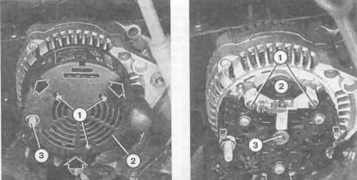
Left: To remove the cover (2) of the Bosch generator, you need to unscrew the three Phillips-head screws (1), remove the B+ wire from the threaded bolt (3) and press out the fastening tabs (arrows).

Right: The voltage regulator (2) is secured with two Phillips head bolts (1). Position (3) indicates the generator rotor axis.


Left: on the removed voltage regulator (4; the illustration shows a new design) the length of the…

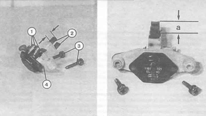
Left: on the removed voltage regulator (4; the illustration shows a new design) the length of the brushes (2) is indicated by arrows. Position (1) shows the voltage regulator contacts, (3) are the mounting bolts.

Right: The illustration shows the measurement of the length of the sliding electrographite contacts on a removed voltage regulator from Bosch of an older design: the brushes should not be shorter than a = 5 mm.


Fold back the regulator so that the carbon brushes do not hang down.


Measure the brush protrusion:
  • the length of the new brushes is 13 mm;
  • minimum length 5 mm.

Valeo generators: remove both regulator mounting screws on the rear of the generator.

Pull out the regulator.

Measure the length of the protruding brushes.

If the remaining length is 5 mm, the brushes are worn out.

Valeo generator brushes cannot be purchased separately; the entire regulator needs to be replaced.

Replacing brushes


Replacing the brushes on the regulators of the new generation of Bosch generators is no longer possible - therefore, carbon brushes are no longer sold as spare parts. If they are worn out, the entire regulator should be replaced. The same can be said about the Valeo generator; carbon brushes are not sold as spare parts - you need to buy a new voltage regulator if the brushes of the old one are worn out.

However, such replacement is possible for old generation Bosch generators. This will require a soldering iron, solder and, in addition, the ability to work with them.

Remove the voltage regulator according to the diagram described above.

Unsolder the multi-wire flexible wires, pull out the carbon brushes.

Remove the pressure springs from the old brushes and put them on the new ones.

Solder multi-wire flexible wires.

When doing this, use a little tin and work quickly so that the wires do not absorb too much tin. Otherwise, they will become stiff.

Hint: If the brushes are removed, you can check the copper contact rings at the same time (brushes run over them). If deep traces of wear are found on them, then they need to be ground down and polished in an auto electrics workshop.


Disconnect the ground wire from the battery, otherwise there is a high risk of a short circuit.

4-cylinder models: remove cover (where is there) pivot bolt at the front of the timing belt cover.

Disconnect the cable to ground, where available.

Loosen the clamp bolt on the generator adjusting bar.

Disconnect the connecting wire.

Loosen and remove the V-belt or poly V-belt.

Loosen and remove the pivot bolt while holding the generator.

Models with 5-cylinder engines: Remove the lower engine compartment protection.

Disconnect the connecting wire.

Remove the mounting bolts and remove the generator.

Models with 6-cylinder engines: Remove the lower engine compartment protection.

Remove the V-belt (description of the work below in this chapter).

Remove the connecting wire and cooling air flow guide from below.

Loosen the mounting bolts and remove the generator.
The article was checked by auto expert Nikita Rudakov
This article is available at russian, bulgarian, belarusian, ukrainian, serbian, croatian, romanian, polish, slovak, hungarian

Share information:
Previous articles
Audi 100 C4: Power devices
Next articles

Voltage regulator
Battery charge indicator
Three phase alternating current generator
Starting an engine with a dead battery
Driving with a faulty alternator
Checking the condition of a V-belt or poly V-belt
Tensioning V-belts and poly V-belts
Tensioning a V-belt or poly V-belt


Similar articles on other Audi car models:
Replacing/checking generator/voltage regulator brushes Audi 80 B3 (1986-1991)
Checking and replacing the generator and voltage regulator… Audi A3 Type 8L (1996-2003)
Self-help with generator and voltage regulator Audi A4 B5 (1994-2001, petrol)
Replacing the generator brushes and voltage regulator Audi A6 C5 (1997-2004)
Repair of manual transmission Audi A8 D2 (1994-2002)
Starter, generator, voltage regulator, splitter 2 terminals 30,… Audi Q5 Type 8R (2008-2017)
Removal and installation the generator bracket Audi A2 (1999-2005)
Link to this page in different formats


Visitor comments

No comments yet


How much will 26 + 17 =


100(C4, 1990-1994) 
  • General information
  • User manual
  • Power unit
  • Engine repair
  • Ignition system
  • Fuel system (gasoline)
  • Fuel system (diesel)
  • Lubrication system
  • Cooling system
  • Exhaust system
  • Transmission
  • Clutch
  • Car gearbox
  • Drive shafts
  • Chassis
  • Car suspension
  • Steering
  • Wheels and tires
  • Brake system
  • Body
  • Ventilation and heating
  • Body repair
  • Electrical equipment
  • Power devices
  • Lighting and appliances
  • Electrical circuits
 
100(C4, 1990-1994, petrol) 
  • General information
  • Operation and maintenance
  • Power unit
  • Engine repair
  • Exhaust system
  • Cooling system
  • Supply system
  • Air filter
  • Mono-Motronic injection system
  • Digifant injection system
  • KE-III-Jetronic and KE-Motronic
  • MPI and MPFI injection system
  • Transmission
  • Clutch
  • Car gearbox
  • Chassis
  • Suspension and steering
  • Brake system
  • Wheels and tires
  • Body
  • Exterior
  • Interior
  • Electrical equipment
  • Fuses and relays
  • Power devices
  • Ignition system
  • Lighting and signaling
  • Equipment and devices
  • Electrical circuits
 
100(C3, 1982-1990) 
  • General information
  • User manual
  • Maintenance
  • Specifications
  • Power unit
  • Engines 4-cylinder
  • Engines 5-cylinder
  • Diesel engine
  • Cooling system
  • Power system (carburetor)
  • Power system (injector)
  • Fuel system (diesel)
  • Transistor ignition system
  • Electronic ignition system
  • Transmission
  • Clutch
  • 4 speed gearbox 014
  • 5 speed gearbox 013 and 093
  • 5 speed gearbox 016 and 012
  • Shift mechanism KP 016
  • Automatic transmission
  • Front wheel drive
  • Chassis
  • Front suspension
  • Rear suspension
  • Steering
  • Brake system
  • Body
  • Body elements
  • Electrical equipment
  • Lighting and appliances
  • Power devices
  • Electrical circuits
 
100(C3, 1982-1990, petrol) 
  • General information
  • Maintenance and operation
  • 4 cylinder engine
  • Engine repair
  • Cooling and lubrication system
  • Supply system
  • Ignition system
  • 5 cylinder engine
  • Engine repair
  • Cooling and lubrication system
  • Supply system
  • Ignition system
  • Transmission
  • Clutch and drive shafts
  • 4 speed gearbox 014
  • 5 speed gearbox 013 and 093
  • 5 speed gearbox 016 and 012
  • Automatic gearbox
  • Chassis
  • Steering
  • Front suspension
  • Rear suspension
  • Brake system
  • Body
  • Body elements
  • Doors, locks and windows
  • Body repair
  • Electrical equipment
  • Equipment and devices
  • Power devices
  • Electrical circuits
 
100(C3, 1982-1990, diesel) 
  • General information
  • User manual
  • Maintenance
  • Troubleshooting
  • Power unit
  • Engine in a car
  • Engine removed
  • Cooling system
  • Fuel system
  • Exhaust system
  • Starting and charging
  • Preheating
  • Transmission
  • Clutch
  • Mechanical gearbox
  • Automatic gearbox
  • Drive shafts
  • Chassis
  • Brake system
  • Suspension
  • Steering
  • Body
  • Exterior
  • Interior
  • Electrical equipment
  • Equipment and devices
  • Electrical circuits
 
AudiManual.ru © 2017-2026 · Mobile version · Feedback · Sitemap: EN BG BY UA RS HR RO PL SK HU · Site search · News and articles
80 B2 · 80 B3 petrol · 80 B3 · 80 B4 · 100 C3 diesel · 100 C3 petrol · 100 C3 · 100 C4 petrol · 100 C4 · A3 Type 8L · A4 B5 petrol · A4 B5 · A4 B6 petrol · A4 B6 · A4 B7 · A4 B8 · A6 C4 · A6 C5 · A6 C5 Allroad · A8 D2 · Q5 Type 8R · Q7 Typ 4L · Audi A2 ·
This site uses cookies 🍪. Click the button to accept this fact.