



Table of contents: Hydraulic block ↓ Speed sensors ↓ Electronic control unit ↓ Relay ↓ Main switch ↓
Hydraulic block
It is located in the engine compartment on the left rear: the hydraulic unit is located between the brake pipes from the master cylinder and the brake pipe to the wheel brakes. In accordance with the commands of the electronic control unit, the pressure in the brake system is maintained constant, reduced or created again. However, this pressure cannot be higher than that created in the master cylinder after the driver presses the brake pedal. The pressure is regulated by four quickly switching electromagnetically driven valves - one per wheel.
If the valves are not supplied with power, the pressure increases. At maximum power supply, the pressure decreases, at medium power supply, the pressure is maintained constant. The pressure decrease phase is especially interesting: since the brake fluid coming from the main brake cylinder cannot simply go into the receiver (otherwise, as a result of this, the brake pedal would simply fail), a powerful return pump pumps brake fluid back to the master cylinder. You can tell by the brake pedal, which begins to pulsate slightly if the return pump is working, meaning the ABS is in effect. If you listen closely, you can also hear the pump noise. Soundproofing in the hydraulic block slightly dampens the sound of the pump. At the top of the hydraulic block, there are two more relays along with the plug connection. The larger of them supplies power to the return pump; the smaller relay controls the electromagnetic valves.
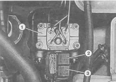
The hydraulic unit (1) of the anti-lock braking system is located in the engine compartment, front left. If you remove the protective cover, you can see the relay of the electromagnetic valves (2) and the relay of the return pump (3).
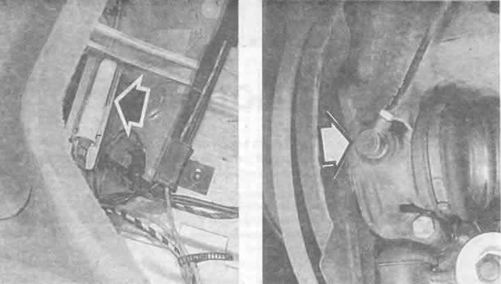
Left: The anti-lock braking system control unit (arrow) is located on the left under the rear seat.
Right: Similar speed sensors (arrow) are located on all four wheels in a vehicle equipped with an anti-lock braking system.
Speed sensors
The rotation speed of each individual wheel is determined by a rotation speed sensor (there are four of them in total) and transmits this information to the control unit. For its part, the control unit gives a command to the hydraulic unit. The speed sensors themselves consist of a magnetic core and a coil and are installed at a small distance from the toothed washer - the rotor. The rotor rotates together with the wheel, which is why the toothed bulges along its perimeter, depending on the speed, pass near the sensor faster or slower. Each tooth running under the sensor causes a short-term increase in voltage in it. Thus, an electrical impulse is created in the sensor, changing its frequency in accordance with the speed of the wheel. This signal is processed in the control unit as information about the speed of rotation.
Electronic control unit
The control unit is located on the left under the rear bench and processes the signals from the speed sensors. At the same time, it controls the hydraulic unit so that the wheels do not lock. In addition to the complex signal processing, the control unit also contains a locking circuit. With its help, the device can check itself, a control lamp lights up on the instrument panel.
Relay
Three relays are involved in the operation of the ABS:
The solenoid valve relay is located under the cover on the hydraulic block.
The return pump relay is also located under the cover on the hydraulic block.
The ABS step relay and surge protection relay are assembled into a combined relay.
Location: on plug field 4 of the additional relay carrier II (chapter "Body electrical system"). Since 7/92 the function of this relay is performed by the ABS control unit.
Main switch
In models manufactured before 6/92, the ABS can be switched off using the ABS master switch located on the switch panel on the instrument panel, in order to achieve some reduction in braking distance in extreme road conditions. For example, if the road is covered with gravel or ice covered with snow, a wedge of gravel or snow is created in front of the tires when braking, which additionally assists braking.
A link to the original source is available on the website AUDImanual.ru