Repair Chevrolet Repair Toyota Repair Honda Repair AvtoVAZ Repair Mercedes-Benz Repair BMW Repair Opel
Home  |  Contacts  |  Sitemap  |    
English Русский
Български
Беларускі
Український
Српски
Hrvatski
Română
Polski
Slovenský
Magyar
AudiManual.ru


  • AUDI 80
  • AUDI 100
  • AUDI A3
  • AUDI A4
  • AUDI A6
  • AUDI A8
  • AUDI Q
  • OTHER
  • ARTICLES
C4 (1990-1994) C4 (1990-1994, petrol) C3 (1982-1990) C3 (1982-1990, petrol) C3 (1982-1990, diesel)

Additional relay block (Audi 100 C4)

  • Home
  • Audi 100
  • C4 (1990-1994, petrol)
  • Electrical equipment
  • Fuses and relays
  • Additional relay block
            0
Relays or control units for which there was no room in the central switch are located in various places in the Audi-100 (so-called additional relay blocks).

The additional relay and fuse box 1 is located on the left rear in the engine compartment. When the…

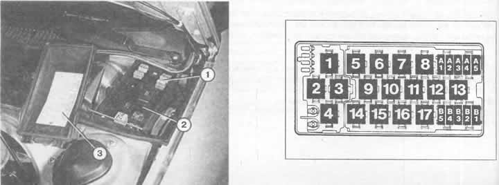
The additional relay and fuse box 1 is located on the left rear in the engine compartment. When the cover (3) is removed, the relays (2) and thermal fuses (1) are visible. Designation:
1 — fan control unit;
2 — relay for electric fan of engine cooling system 1 stage;
3 - relay for electric fan of engine cooling system 2 stages;
4 - relay for fog lights;
5 — relay for disabling the electronic differential lock;
6 — intensive glass washing control unit;
7 - free;
8 - relay for all-wheel drive reverse lights with automatic transmission);
9 — magnetic clutch engagement relay (automatically or manually);
10 — magnetic clutch control unit (manual air conditioner);
11 — Windscreen cleaning/washing system relay;
12 - free;
13 — relay for adjusting the current in the speakers;
14, 15 — light bulb control unit;
16 - free;
17 — relay for air conditioner standby mode (manual air conditioner);
B1 - Thermal fuse I for seat position adjustment;
B2 - Thermal fuse II for seat position adjustment;
VZ — thermal fuse for the thermostat of the heated closing cylinder;
B4 - Thermal fuse for trailer plug socket;
B5 - free;
A1 - Thermal fuse for electric windows;
A2 - Thermal fuse for central locking system, anti-theft system, infrared ray control unit;
AZ - Thermal fuse for electrically sliding sunroof;
A4 - Thermal fuse for radio/speakers;
A5 - thermal fuse for seat heating.


Right: under the trim (1) on the left in the driver's footwell is the additional relay block II…

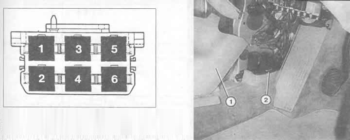
Right: under the trim (1) on the left in the driver's footwell is the additional relay block II (2). List of designations for the upper figure:

1 - control unit for window lifters and sliding sunroof;
2 — control unit for window lifters and sliding sunroof;
3 - Relay for power windows and sunroof;
4 - overvoltage protection relay (airbag), ABS combination relay;
5 — automatic transmission lever lock control unit;
6 - relay for automatic transmission.


The additional relay block I is located on the left rear in the engine compartment in the so-called waterproof housing. In addition to numerous relays and control units, various thermal fuses and connections for connecting diagnostic equipment are also located here (see chapter "Regular maintenance").


The additional relay block II is located under the side trim on the left in the driver's footwell. To do this, remove the Phillips-head screws from below, then remove the cover. Remove the Phillips-head screws from the side trim and carefully remove them.

The additional relay block III is located under the right side trim panel in the area of the feet of the passenger sitting next to the driver, i.e. to a certain extent "mirror" to the position of the additional relay block II. Removing the trim panel is the same as for the additional relay block II.

Note: The cover of the waterproof housing of the additional relay unit I must be closed, otherwise draughts will blow through the driver's legs while driving. This is often forgotten after diagnostics in the auto repair shop.


Read the original source on the website AUDImanual
The article was checked by auto expert Nikita Rudakov
This article is available at russian, bulgarian, belarusian, ukrainian, serbian, croatian, romanian, polish, slovak, hungarian

Share information:
Previous articles
Audi 100 C4: Fuses and relays
Next articles

Central switchboard
Plug connections
Wires
Orientation in the electrical system
Ignition system unit
Relays and control units
Unloading relay contact X
Fuses


Similar articles on other Audi car models:
Placing the relay on the mounting block Audi 80 B2 (1979-1986)
Removal and installation an additional resistor Audi A3 Type 8L (1996-2003)
Additional relay support Audi A4 B5 (1994-2001, petrol)
Electrical diagram of the control unit of the direct injection… Audi A6 C5 (1997-2004)
Additional relay bracket in the luggage compartment Audi A8 D2 (1994-2002)
Block J519. Headlight washer relay, bonnet contact switch, fog… Audi Q7 Typ 4L (2005-2015, diesel)
Removal and installation a 3-pin relay block Audi A2 (1999-2005)
Link to this page in different formats


Visitor comments

No comments yet


How much will 28 + 20 =


100(C4, 1990-1994) 
  • General information
  • User manual
  • Power unit
  • Engine repair
  • Ignition system
  • Fuel system (gasoline)
  • Fuel system (diesel)
  • Lubrication system
  • Cooling system
  • Exhaust system
  • Transmission
  • Clutch
  • Car gearbox
  • Drive shafts
  • Chassis
  • Car suspension
  • Steering
  • Wheels and tires
  • Brake system
  • Body
  • Ventilation and heating
  • Body repair
  • Electrical equipment
  • Power devices
  • Lighting and appliances
  • Electrical circuits
 
100(C4, 1990-1994, petrol) 
  • General information
  • Operation and maintenance
  • Power unit
  • Engine repair
  • Exhaust system
  • Cooling system
  • Supply system
  • Air filter
  • Mono-Motronic injection system
  • Digifant injection system
  • KE-III-Jetronic and KE-Motronic
  • MPI and MPFI injection system
  • Transmission
  • Clutch
  • Car gearbox
  • Chassis
  • Suspension and steering
  • Brake system
  • Wheels and tires
  • Body
  • Exterior
  • Interior
  • Electrical equipment
  • Fuses and relays
  • Power devices
  • Ignition system
  • Lighting and signaling
  • Equipment and devices
  • Electrical circuits
 
100(C3, 1982-1990) 
  • General information
  • User manual
  • Maintenance
  • Specifications
  • Power unit
  • Engines 4-cylinder
  • Engines 5-cylinder
  • Diesel engine
  • Cooling system
  • Power system (carburetor)
  • Power system (injector)
  • Fuel system (diesel)
  • Transistor ignition system
  • Electronic ignition system
  • Transmission
  • Clutch
  • 4 speed gearbox 014
  • 5 speed gearbox 013 and 093
  • 5 speed gearbox 016 and 012
  • Shift mechanism KP 016
  • Automatic transmission
  • Front wheel drive
  • Chassis
  • Front suspension
  • Rear suspension
  • Steering
  • Brake system
  • Body
  • Body elements
  • Electrical equipment
  • Lighting and appliances
  • Power devices
  • Electrical circuits
 
100(C3, 1982-1990, petrol) 
  • General information
  • Maintenance and operation
  • 4 cylinder engine
  • Engine repair
  • Cooling and lubrication system
  • Supply system
  • Ignition system
  • 5 cylinder engine
  • Engine repair
  • Cooling and lubrication system
  • Supply system
  • Ignition system
  • Transmission
  • Clutch and drive shafts
  • 4 speed gearbox 014
  • 5 speed gearbox 013 and 093
  • 5 speed gearbox 016 and 012
  • Automatic gearbox
  • Chassis
  • Steering
  • Front suspension
  • Rear suspension
  • Brake system
  • Body
  • Body elements
  • Doors, locks and windows
  • Body repair
  • Electrical equipment
  • Equipment and devices
  • Power devices
  • Electrical circuits
 
100(C3, 1982-1990, diesel) 
  • General information
  • User manual
  • Maintenance
  • Troubleshooting
  • Power unit
  • Engine in a car
  • Engine removed
  • Cooling system
  • Fuel system
  • Exhaust system
  • Starting and charging
  • Preheating
  • Transmission
  • Clutch
  • Mechanical gearbox
  • Automatic gearbox
  • Drive shafts
  • Chassis
  • Brake system
  • Suspension
  • Steering
  • Body
  • Exterior
  • Interior
  • Electrical equipment
  • Equipment and devices
  • Electrical circuits
 
AudiManual.ru © 2017-2026 · Mobile version · Feedback · Sitemap: EN BG BY UA RS HR RO PL SK HU · Site search · News and articles
80 B2 · 80 B3 petrol · 80 B3 · 80 B4 · 100 C3 diesel · 100 C3 petrol · 100 C3 · 100 C4 petrol · 100 C4 · A3 Type 8L · A4 B5 petrol · A4 B5 · A4 B6 petrol · A4 B6 · A4 B7 · A4 B8 · A6 C4 · A6 C5 · A6 C5 Allroad · A8 D2 · Q5 Type 8R · Q7 Typ 4L · Audi A2 ·
This site uses cookies 🍪. Click the button to accept this fact.