
Design
The hydraulic pusher consists of two main moving parts: the pusher itself 2 (see picture), serving simultaneously in the process of work of the plunger, and cylinder 4.
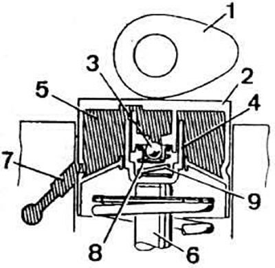
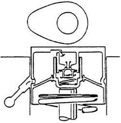
Sectional view of hydraulic tappet: 1 — camshaft cam; 2 - pusher; 3 - check valve; 4 — cylinder; 5 - accumulation chamber; 6 — valve; 7 — oil supply channel to the pusher; 8 - high pressure chamber; 9 — valve clearance compensation spring
Under the pressure of spring 9, the plunger and cylinder move away from each other, due to which the gap between the camshaft cam and the end of the valve stem is selected.
Filling and locking of the high-pressure chamber 8 is ensured by the check valve 3.
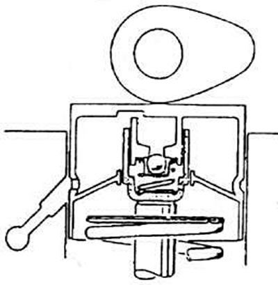
Valve lift start moment
Operating principle
Valve lift start moment
At the moment the camshaft cam hits the valve stem, the check valve closes the chamber and the pressure in it increases. The increase in pressure does not lead to compression of the volume occupied by oil in the high-pressure chamber. The tappet thus works as a solid body.
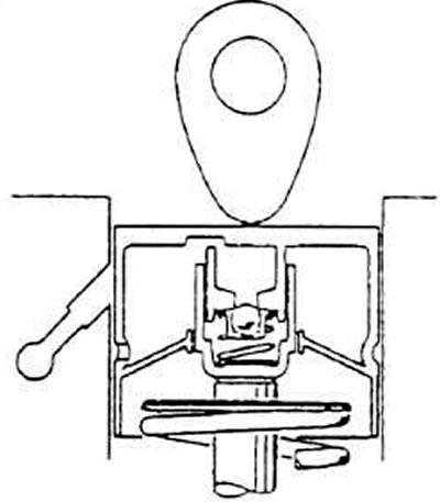
Moment of maximum valve lift
Valve lift moment
The camshaft cam presses forcefully on the tappet, which leads to a significant increase in the pressure 8 of the tappet cavity. A small amount of oil is ejected through the leaks between the cylinder and the plunger, which leads to compression of the hydraulic tappet by a maximum of 0.10 mm. Such compression is structurally necessary for running in the tappets even with a decrease in the distance between the camshaft cam and the tappet end.
Valve clearance compensation
The camshaft cam does not press on the tappet, and the pressure in the high-pressure chamber drops. The spring separates the plunger and the cylinder, thereby compensating for the gap between the cam and the end of the valve stem.
Valve clearance compensation
At this point, the check valve opens, and some amount of oil enters the high-pressure chamber. This amount corresponds directly to the gap being compensated.
Note. The valve train noise after the engine is started is normal. This is due to the fact that when the engine is stopped, some of the oil flows out of the tappet cavity. When the engine starts, the high-pressure chamber is filled again and the noise stops. Filling of the high-pressure chamber continues until the engine warms up to operating temperature.
The design of the cylinder head lubrication circuit eliminates the complete removal of oil from the channels after the engine is stopped. This ensures that oil is supplied to the tappets immediately after the engine is started and that noise in the valve mechanism drive ceases as quickly as possible.
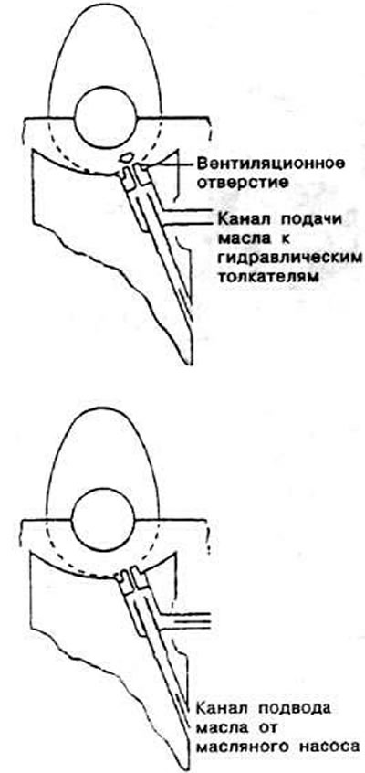
Operation of hydraulic tappets at the moment of engine start
After the engine is stopped, oil flows out of the channels coming from the oil pump, and the channels supplying oil to the tappets remain filled with oil. To prevent air from entering the tappet cavity under the action of oil pressure when the engine is started, there are ventilation holes in the channels supplying oil to the tappets, which provide automatic purging of the tappet cavity. In addition, the ventilation hole allows reducing the pressure of the oil entering the tappets.
Checking the technical condition of hydraulic tappets
The hydraulic tappet design is non-disassemblable and cannot be repaired.
Start the engine and let it run until the electric cooling fan turns on for the first time.
Maintain the engine speed at 2500 rpm for 2 minutes.
If you hear noise in the valve train, determine the faulty tappet as follows:
- remove the cylinder head cover;
- turn the engine crankshaft clockwise by the pulley mounting bolt so that the camshaft cam heads corresponding to the valves of the cylinder being checked are facing the hydraulic tappet;
- press the plunger with a wooden or plastic wedge and measure the free travel of the plunger, which should be no more than 0.10 mm before the valve opens. If it is more, the plunger must be replaced.
Warning: After installing a new tappet, pre-filled with oil and bled, the engine may not be started earlier than 30 minutes later to prevent the valves from hitting the pistons.