
Table of contents: Cylinder head gasket ↓ Valve seats ↓ Valve guide bushings ↓ Valves ↓ Clearances in the valve drive… ↓ Valve springs ↓ Pushers ↓
The cylinder head is cast from aluminum alloy. The valve seats and guides are pressed into the cylinder head. The DS engines from September 1985 and the NP engines are equipped with a cylinder head with hydraulic tappets, providing automatic compensation of valve clearances.
Warpage of the mating plane of the head with the cylinder block, no more than, mm: 0.1.
Permissible height of the cylinder head after grinding, not less than, mm: 132.60.
Cylinder head gasket
The cylinder head gasket has the inscription "oben" (top). The plane with this mark must face the cylinder head during assembly.
Valve seats
The valve seats are made of powder metallurgy steel and are not replaceable. If traces of burning or wear are found that cannot be removed by grinding, the cylinder head is replaced as a whole.
Valve seat characteristics
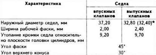
* The value in brackets is for engines of the "DS" model from September 1985 and the "NP" model
Valve guide bushings
The valve guides are made of special brass and pressed into the cylinder head.
Maximum permissible marginal clearance (when worn out), between valve stem and guide bushing, mm:
- for intake valves: 1.0;
- for exhaust valves: 1.3.
Diameter of the hole in the valve guide bushings, mm 8.013-8.0.35.
Valves
The valves are arranged in the head in parallel in one row above the cylinders vertically and are actuated directly by the camshaft cams via tappets (engines of the "DR" model) or via hydraulic tappets (engines of the "DS" or "NP" model). The exhaust valves are not subject to grinding.
Valve characteristics
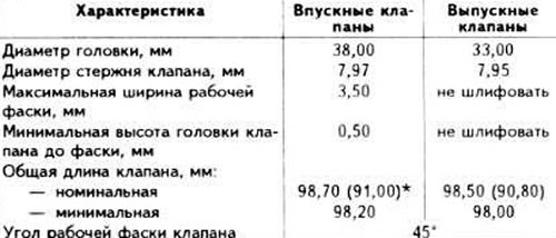
* The values in brackets are for the "NP" model engine.
Clearances in the valve drive mechanism
Engines of the models "DR" and "DS" (until September 1985.)
The clearance between the camshaft cams and the adjusting washers at a coolant temperature above 35°C should be 0.25±0.05 mm for the intake valves and 0.45±0.05 for the exhaust valves; on a cold engine, 0.20±0.05 and 0.40±0.05 mm, respectively.
The gap is adjusted by selecting the thickness of the adjusting washers installed on the upper ends of the pushers.
Spare parts include adjusting washers with a thickness of 3.00 to 4.25 mm at intervals of 0.05 mm.
Engines of "DS" models (since September 1985.) and "NP"
Clearances in the valve drive mechanism are adjusted automatically by hydraulic tappets.
Valve springs
Each intake and exhaust valve has two springs. The springs are the same for both intake and exhaust valves.
Pushers
The valve tappets are located directly in the cylinder head. On the upper ends of the tappets of the "DR" and "DS" engines (until September 1985.) adjusting washers of different thicknesses are installed to adjust the thermal clearances of the valves.
(A link to the original source is available on the website: AUDIMANUAL)