
Table of contents: Removal ↓ Bulkhead ↓
Removal
1. The generator can be located in front, on the right or left side of the engine (depending on its type) and is driven by a belt from a pulley on the front end of the crankshaft. Apply the handbrake, then jack up the front of the car and place it on axle stands. Remove the lower engine guard.
2. Disconnect the negative cable from the battery (see Chapter 3).
3. Remove the auxiliary drive belt from the alternator pulley.
4. Disconnect the charge indicator light wiring from the alternator. On some models, you may need to remove the plastic cover to gain access to the rear of the alternator.
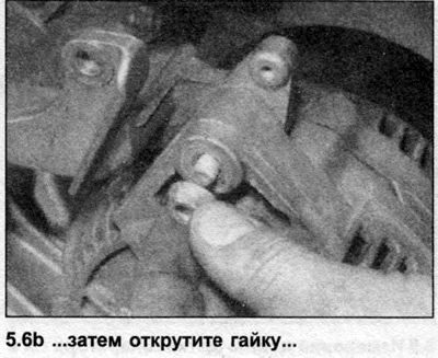
5. Remove the protective cover and unscrew the nut, then disconnect the positive wire from the generator terminal.
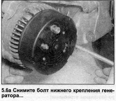
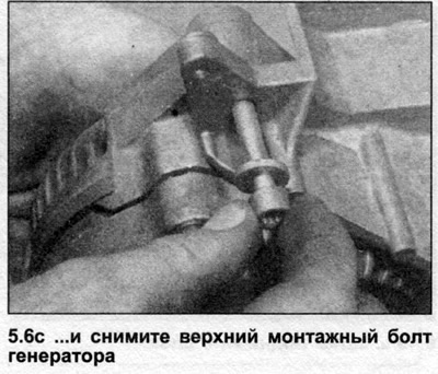
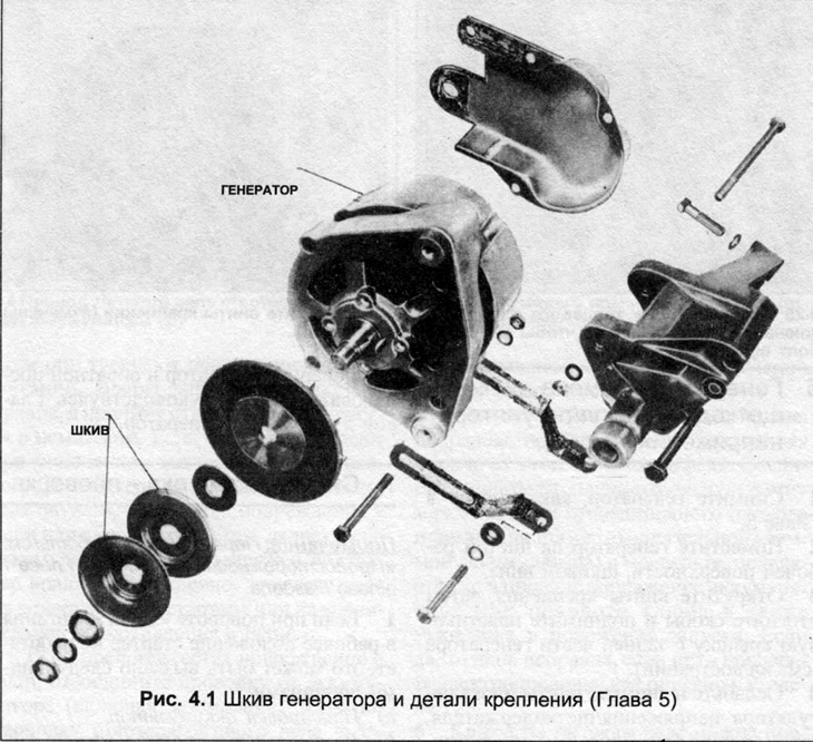
6. Loosen and remove the lower and then upper mounting bolts, then remove the generator from the bracket (see illustrations).
Bulkhead
Note: The voltage regulator and brushes can be removed without removing the alternator. However, the following disassembly procedure requires removal of the alternator.
7. Clean the generator from dirt.
8. Unscrew the screws, remove the voltage regulator and brushes. If the length of the brushes is less than the specified minimum length, they must be replaced with the voltage regulator assembly.
9. Mark the alignment of the casing and stator relative to each other.
10. Clamp the pulley in a vice, unscrew the nut and remove the washer, pulley and fan with gaskets.
11. Loosen the tie bolts and remove the front casing with the rotor.
12. Remove the rotor from the front casing, remove the gaskets.
13. Remove the mounting plate and screws. Knock the bearing out of the front housing with a soft metal drift.
14. Remove the bearing from the end of the rotor, being careful not to damage the generator rings.
15. Unscrew the screw, disconnect the contact, remove the capacitor from the rear casing.
16. Remove the clamp nuts, then remove the washers, gaskets and insulator from the rear housing.
17. Carefully separate the stator from the rear casing without disconnecting the wire. Mark the location of each wire, unsolder them, try not to overheat so as not to damage the diodes. Long-nose pliers can be used as a heat sink.
18. Remove the screws, separate the diode plate from the rear casing.
19. Remove the wave gasket from the rear casing.
20. Ring out the stator windings by connecting an ohmmeter or test lamp between each wire and the outer ring. There should be no short circuit. Check the internal resistance between the wires and compare with the data in the Specifications by connecting the ohmmeter between wires 1 and 2, then 1 and 3, and 2 and 3 - the numbering of the wires does not matter.
21. Using an ohmmeter, measure the resistance of each diode and compare it with the data in Specifications, connecting an ohmmeter to the diode terminals in one direction. Reverse the wires and check that there is no resistance in the other direction.
22. Check the rotor windings for short circuits by connecting an ohmmeter or test lamp between each slip ring and the core of the winding. Measure the internal resistance of the winding and compare with the data in Specifications, connecting an ohmmeter between the two springs.
23. Clean all components, prepare new bearings, brushes, etc.
24. Assembly is carried out in reverse order.
Installation
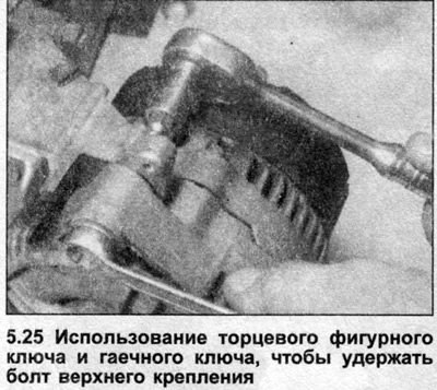
25. Install in reverse order, tighten the mounting bolts securely (see illustration).
[The original article is available on the website: audimanual]