
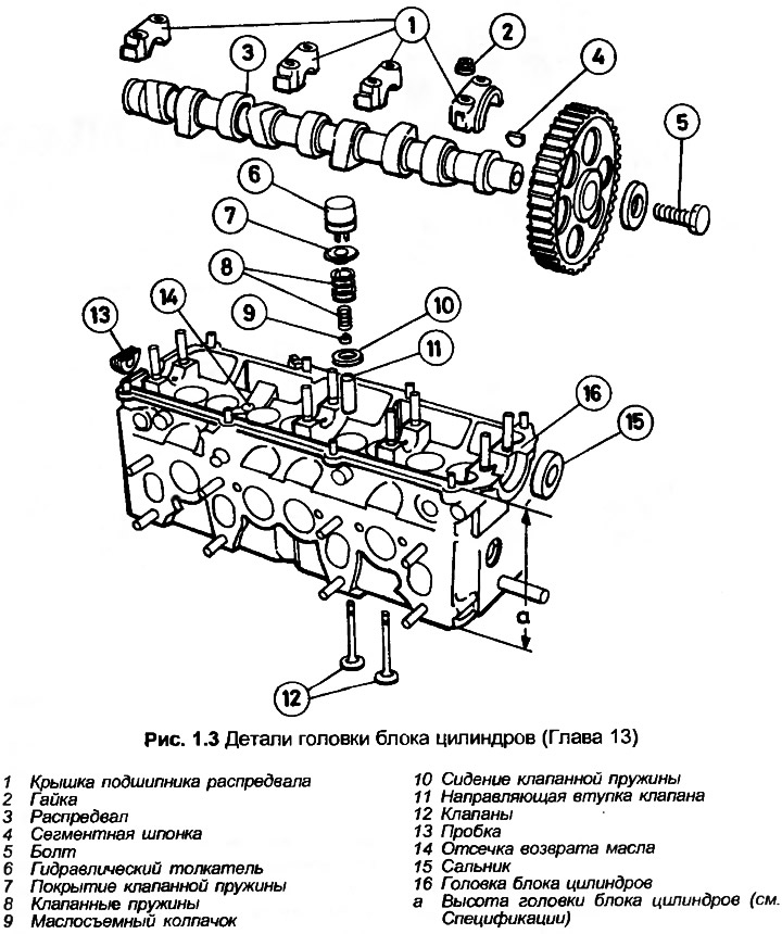
1. Having removed the cylinder head as previously described, the valves can be removed as follows. The valves are deeply embedded in the top of the cylinder head and therefore require a valve spring puller with long claws to remove them. One method is to use a tube of approximately the same diameter as the valve spring cover and of sufficient length. To remove the valve locks, cut a slot in the tube on each side so that three quarters of a circle remain.
2. Prepare a tray with holes for the number of valves and labeled accordingly so that each valve and related parts can be stored separately as they are removed. Inlet valves are #2 - 4-5 - 7, outlet valves are #1 - 3-6 - 8, numbered from the timing belt.
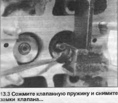
3. Compress each valve spring until the valve locks are removed (photo). Remove the valve locks, release and remove the spring compressor.
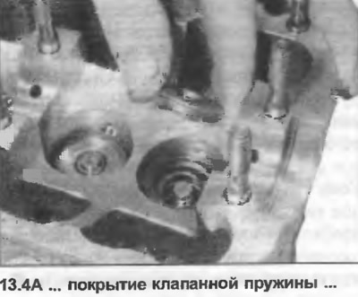
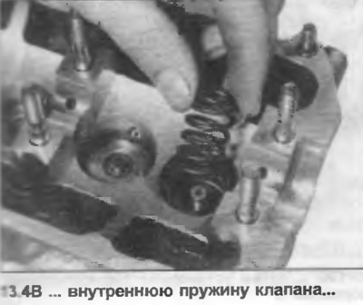
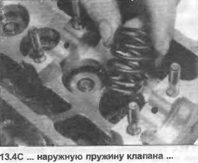
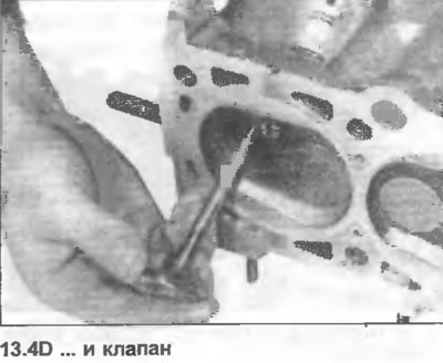
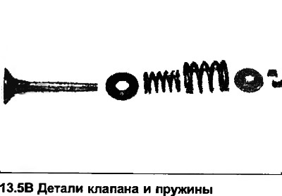
4. Remove the valve spring cover, inner and outer springs and valve (photo). It is good practice to store the valve springs so that when installing them, they are oriented as they were before removal.
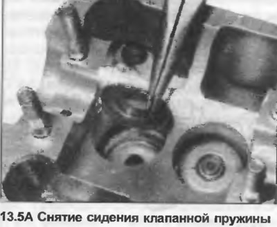
5. Remove and discard the valve stem seals, then remove the valve spring seat (photo).
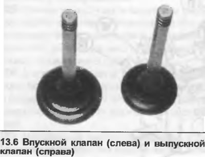
6. Check the condition of the valve heads for pitting and burnt areas, paying special attention to the exhaust valve heads (photo). Also check the valve seats. If there is slight pitting on the valve and seat, it can be removed by grinding the seat and valve infusion. Otherwise, it will be necessary to replace the valve and grind down the valve seat. Do not grind down the valve head.
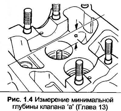
7. If the valve seat is ground off, it is important to determine the maximum amount of metal that can be removed from the seat. If more than the permissible amount is removed, the hydraulic lifters will not function properly. Insert the valve into the guide and press it firmly against the seat. Now measure the distance from the end of the valve stem to the top surface of the cylinder head (Fig. 1.4). The minimum permissible distance is 33.80 mm for intake valves and 34.10 mm for exhaust valves. Now it is possible to calculate the maximum amount of metal that can be removed before grinding the seat off. If the valve seat is excessively worn and grinding is not possible, the cylinder head must be replaced.
8. The valves are lapped as follows. Apply a small amount of lapping compound around the valve contact surface or seat, insert the valve into the guide. Mount the vacuum lapping tool on the valve head and grind the valve with a semi-rotary motion. When resistance is felt, remove the valve, rotate and repeat the action until a uniform matte gray surface is obtained over the entire bearing surface area of the head and valve seat.
9. Clean all carbon deposits from the valve head and valve stem. Carefully remove any remaining paste, trying not to leave it in the channels or in the guide bushings. Wipe the valves and seats with a kerosene-soaked rag, then with a clean, dry rag.
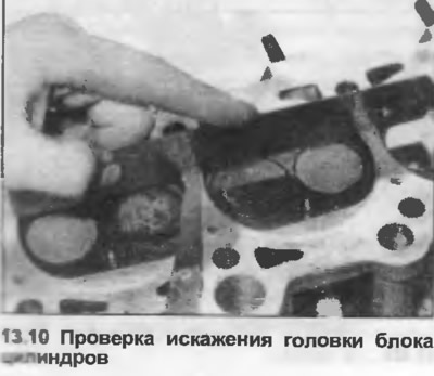
10. Clean the cylinder head completely, then check its distortion by placing the edge of a ruler in several places, longitudinally, transversely and diagonally, and measuring the gap under it with feeler gauges (photo). If the gap exceeds the limit given in the Specifications, consult an Audi dealer before replacing the head. When resurfacing, the height of the cylinder head must not be less than the minimum value given in the Specifications.
11. Examine the cylinder head to see if there are any cracks. If there are small cracks between the valve seats or at the bottom of the spark plug holes, no more than 0.5 mm wide, the head can be reused, but the cylinder head cannot be restored or new valve seat inserts installed.
12. Check the condition of the valve guides. First clean the guide, then insert the new valve stem into the guide. Due to the different diameters of the valve stems, make sure to use only the intake valve for checking the intake valve guides and the exhaust valve for the exhaust valve guides. With the end of the valve stem aligned with the top of the valve guide, measure the total lateral offset of the valve head housing. If the offset exceeds the maximum value given in the Specifications, new guides must be installed, but this is a job for an Audi dealer or specialist, as it requires special equipment.
13. To install the valves, lubricate the valve stem and insert the valve into the guide.
14. Position the valve spring seat on the guide.
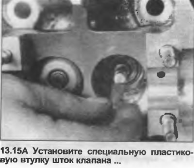
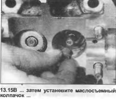
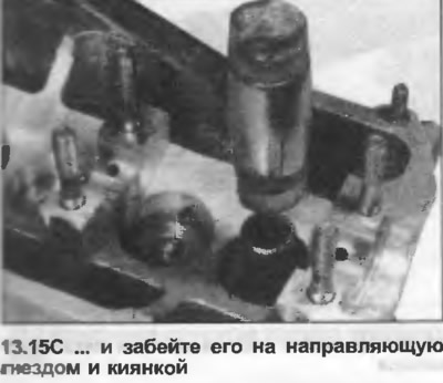
15. Place the special plastic sleeve on the end of the valve stem, then dip the new valve stem seal into the oil and slide it over the valve stem onto the guide. If there is no plastic sleeve, wrap thin adhesive tape around the top of the valve stem so that it covers the recess for the valve locks. This will prevent damage to the valve stem seal. Remove the sleeve or tape after installing the seal. A socket and a light mallet can be used to install the seal onto the guide (photo).
16. Install the inner and outer valve springs, then the valve spring cover. Springs on any valve should only be replaced in pairs.
17. Install the puller and compress the spring only enough to install the valve locks. If the spring is compressed more than necessary, there is a risk of damaging the valve stem seal.
18. Install the valve locks, release the spring compressor slightly and check that the valve locks are positioned properly, then remove the compressor.
19. Hit the top of the valve stem with a hammer to check that the valve locks are positioned correctly.
20. Repeat the procedure for all valves.